Qucs — почти универсальный симулятор электронных цепей
Содержание:
- Solve Elec
- PECS
- 9: Spicy schematics
- Quantum Mechanics
- For Developers
- Logic Gate Simulator
- QUCS
- idealCircuit
- SIMetrix/SIMPLIS
- Every Circuit
- EasyEDA — дизайн электронной цепи, моделирование цепи и PCB дизайн:
- 8: TinaCloud
- Deeds (Digital Circuit Simulator)
- Бесплатные программы
- MultiMedia Logic
- Sensors, Transducers and Interactions with the External World
- High Frequency Circuits
- Logical Circuit
Solve Elec

Solve Elec is a circuit simulator and solver software. It can not only simulate, but solve circuit for you. After circuit simulation, it lets you view circuit properties, circuit equations, and circuit graphs. You can view versus graphs between different circuit parameters, such as: E1 vs R1, E1 vs E2, R2 vs I1, and more.
There are two modes for circuit design here: AC mode and DC mode. Design an AC circuit or a DC circuit. Components available are voltage sources, current sources, Resister, Capacitor, Inductor, Diode, LED, Measurement devices, etc.
Save a circuit to load and simulate later in .eln format.
This electric circuit simulator software is perfect for students.
PECS
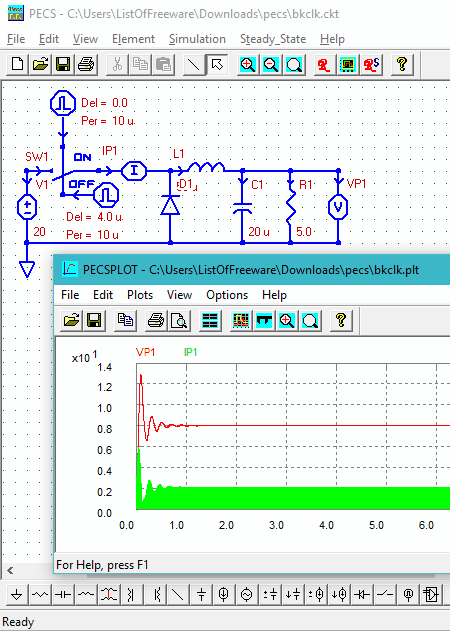
PECS is a free Power Electronics Circuit Simulator software. It can be used to simulate power electronics circuits with electrical and electronic components. A wide list of components are available in this circuit simulation tool. After designing circuit, you can not only simulate it, but can view output waveform. If you have a circuit saved on your computer in .ckt format, then you can open and simulate it here.
The components are known as Elements here. The list of elements contains:
- Various types of voltage sources: VDC, VAC, IDC, VCVS, VCIS, ICIS, etc.
- Basic circuit elements: R, L, C, Transformer, Wire, Ground, etc.
- Switch Control elements: Clock, Modulator, Upper limiter, Lower limiter, Threshold, and VCO.
- Other components: Switch, Diode, Op-Amp, and multiplier.
It is another good option if you are looking for an electronic circuit simulator.
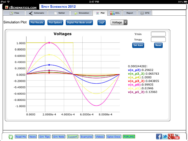
9: Spicy schematics
Spicy использует Ngspice для моделирования и является первым приложением, предлагающим синхронизацию файлов между iPad и вашим компьютером PC/ Mac / Linux или Chromebook. Схемы создаются, сохраняются, отображаются локально. Интернет используется только для составления списков и моделирования. Есть надежная и мощная многосерверная система, которая может обрабатывать тысячи одновременных соединений.
Spicy имеет бесплатную веб-версию для браузера Chrome, а также предлагается в качестве первого приложения Facebook для схемотехнического проектирования и моделирования. Программа также предлагает расширенные функции, такие как Онлайн-библиотека схем (функция в приложении), где можно бесплатно загружать модели Spice других пользователей и свои собственные.
Quantum Mechanics
|
Hydrogen Atom Applet |
|
|
Molecular Orbitals Applet |
|
|
1-D Quantum Mechanics Applet |
|
|
1-D Quantum Crystal Applet |
|
|
2-D Quantum Crystal Applet |
|
|
1-D Quantum Transitions Applet |
|
|
Atomic Dipole Transitions Applet |
|
|
2-D Rectangular Square Well Applet |
|
|
2-D Circular Square Well Applet |
|
|
2-D Quantum Harmonic Oscillator Applet |
|
|
Quantum Rigid Rotator Applet |
|
|
3-D Quantum Harmonic Oscillator Applet |
For Developers
This application was developed, with permission, from the Java circuit
simulator by Paul Falstad. I always found this a great tool to help visualize
circuits and loved the interactive nature compared to normal SPICE
implementations. However, I never really liked Java in the browser and
with recent security problems and consequent changes in security
policy by browser vendors it seemed to me that there would be a lot of
benefit in having a version that didn’t require plug-ins.
To create this version I modified the original Java to run in the
Google Web Toolkit (GWT). Most of the user interface was rewritten but
the technical parts of the simulation are almost untouched. The total work on this project took just over a month.
Thanks to the kind permission of Paul Falstad the source project for this version of the application is now available on GitHub under a GPLv2 license.
Logic Gate Simulator
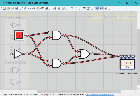
Logic Gate Simulator is an open source circuit simulation software. It lets you design logic circuits, simulate them, and view output on oscilloscope.
You can either load a .gcg format circuit or design one from scratch. For logic circuit design, various components are available. The interface is arranged in a very good manner, making it easy for you to design a circuit. You will find lists of Basic gates, Compound gates, and Input/Output gates. You can also create custom IC by joining a group of components and save it to use later.
A design can be saved in .gcg format, or you can export you design as image. You can also take a printout of your design.
Logic Gate Simulator is exclusively designed to create and simulate logic circuits.
QUCS

QUCS or Quite Universal Circuit Simulator, as the name says, can simulate almost any type of circuit. It is an open source circuit simulator.
Either you design an electrical circuit, or an electronic circuit, this software has components for both. Be it resistor, capacitor, voltage source, current source, probes, transmission lines, transistors, amplifiers, diodes, comparater, flip flops, or simulators, you will find it all here. Design a circuit and simulate it. If there’s any error, it shows up. If there’s no error, the circuit is simulated and circuit parameters are displayed.
QUCS is a very good alternative to the above mentioned software, such as: TINA-Ti, idealCircuit, etc.
idealCircuit
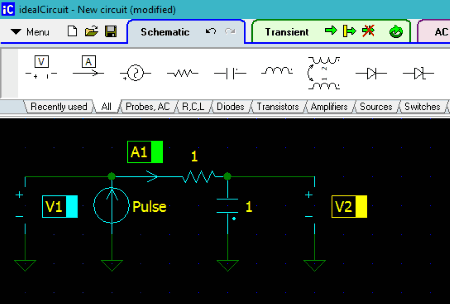
idealCircuit is an amazing circuit simulation software. It lets you carryout electrical circuit simulation as well as electronic circuit simulation. Most of the software listed here provide either of the simulation options, so this can be your pick if you need both electronic and electric circuit simulator software. Another impressive feature about this software is that, there are 3 tabs available here for circuit design, simulate and view resultant waveform, and to view AC parameters of the simulated circuit.
You get a good list of components to design circuit. You can also load a circuit in .ic format to simulate it. Let us checkout the list of components:
- Probes: Voltmeter, Ammeter, and AC source.
- RCL: Resistor, Capacitor, Inductor, and Coupled inductor.
- Diodes: Diode, Zener, Bidirectional Zener, and Bridge rectifier.
- Transistors: NPN, PNP, N-FET, and P-FET.
- Amplifiers: Buffer, Comparator, Differential amp, Differential comparator, and Summing amp.
- Sources: Voltage sources and Current sources.
- Switches: Normat switch, Logic/Current/Voltage controlled switch, SPDT switches, etc.
- Transformers: Winding or Transformer set.
- Logical: Logical gates like AND, OR, NOR. XOR, etc., Flipflops, Trigger generator, Schmitt trigger, etc.
After designing a circuit, simply go to the Transient tab and click on the Start Transient option to view the simulated waveform. The AC tab displays the output AC parameters of the circuit.
To see how to simulate circuit using this freeware, you can load the pre-loaded designs available and simulate them.
SIMetrix/SIMPLIS
SIMetrix/SIMPLIS lets you design and simulate electrical as well as electronic circuits. Just like idealCircuit, you can simulate electric circuit, power electronic circuit, and logic circuit. A good list of components make this software worth a try. Circuit simulation not only provides values of voltage and current across components, but also provides transient waveform analysis.
In the list of components, you will find active components, passive components, transformers, connectors, probes, voltage sources, current sources, semiconductors, logic gates, amplifiers, transistors, and more.
The simulator menu has options to carry out analysis, run schematic, check if the circuit is complete, etc. You can also view transient waveform of the circuit once simulated.
Its a complex, yet very extensive circuit simulation software with loads of tools, components, and analysis options.
Every Circuit
Поддерживает всё что мне нужно, может я и не самый лучший радиоинженер, но вот радиоэлемента увлекаюсь еще в ого. Qucs полезная программа.
И именно тут я смог Qucs скачать на русском языке!
OrCAD Самая популярная программа компании Cadence, содержащая полную среду для коммерческих проектов PCB, содержит все компоненты, необходимые для проектирования печатных плат, такие как: модуль для введения схем; редактор печатных плат с интегрированным управлением проектирования. Ответить Ответить с цитатой Цитировать Татьяна
Времени и трудозатрат по определению меньше. В данном обзоре рассмотрим 3 самых популярных симулятора электрических цепей для Андроид устройств, сравним их возможности, потенциал и удобство использования.
Бесплатная версия программы не позволяет создавать электронные схемы в коммерческих целях. EAGLE является аббревиатурой для легко применимого графического редактора макетов, что означает простой в использовании графический редактор.
Измерения параметров электронной схемы продемонстрируют с реалистичными виртуальными инструментами. Бесплатная версия программы не позволяет создавать электронные схемы в коммерческих целях. К сожалению, в данном симуляторе нет транзисторов. Практически как на настоящем мультиметре, можно измерить множество параметров.
Droid Tesla
Пригодится она и для разработки оптимальных решений для электрических плат. Суммарное напряжение последовательно соединенных батареек 3 вольта.
EasyEDA — Сервис по созданию электронных схем и печатных плат онлайн
EasyEDA — дизайн электронной цепи, моделирование цепи и PCB дизайн:
Вероятно, вам придется перечислить и наклеить эти ярлыки в сторону с соответствующим окружением на компоненте. Соединение элементов электрической схемы.
Rapid Symbol Creation: Draw generic rectangular symbols for IC or system-level wiring diagrams with just a few clicks. Программа для черчения и анализа схем Micro-Cap платная, в оригинале — англоязычная, но есть и русифицированная версия. Скачать и получить более подробную информацию с обучающей книгой вы можете на нашем сайте.
Это устройство, основанное на вспышке, с некоторой схемой выборки и учебным пособием.
Таким образом, путем последовательных перемещений необходимых элементов, и соединяя их между собой, создается электрическая схема. Язык русский, разобраться в ней можно быстро, но чтобы понять все функции придется потратить не одну неделю. Имеется возможность импорта файлов из популярных САПР. И еще один положительный момент: есть много видео-уроков работы с Компас-Электрик, так что освоить ее будет несложно.
Читайте дополнительно: Расчет петли фаза ноль с помощью чайника
Благодаря доступу к приложениям в облаке мы получаем удобство, мобильность и совместимость между устройствами. Веб-ссылка содержит файл изображения схемы внутри веб-страницы и доступна для просмотра в стандартном веб-браузере. Пользователю потребуется только добавить компоненты, связать их и отправить плату в печать, предварительно настроив ее. Разрабатывалась она в России, потому полностью на русском.
В то же время в спецификации появляются параметры название, номер, номинал выбранного элемента. Что приятно, что можно легко менять масштаб — прокруткой колеса мышки.
Он работает на наших серверах в любом интернет-браузере. В этом окне можно менять любые атрибуты элемента схемы. У данного продукта также есть полностью русифицированная версия, причем с хорошим уровнем перевода. Все они чем-то похожи, но и имеют свои уникальные функции, благодаря которым и становятся популярными у широкого круга пользователей. Когда вы убедитесь функцию цепи хорошо, вы будете создавать печатную плату с тем же программным обеспечением.
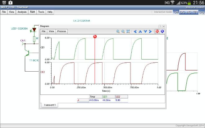
8: TinaCloud
TINA – это хорошо продуманный, но доступный программный пакет для построения электросхем, проектирования печатных плат для анализа, проектирования и тестирования в реальности аналоговых, цифровых, HDL, MCU и смешанных электронных схем и их печатных плат.
Программа позволяет анализировать SMPS, RF, коммуникационные и оптоэлектронные схемы, генерировать и отлаживать код MCU, используя встроенный инструмент потоковой диаграммы и тестирование приложений микроконтроллеров в смешанной среде.
Главная особенность TINA заключается в том, что можно не только нарисовать электросхему онлайн, но и воплотить ее в жизнь с помощью дополнительного оборудования LabXplorer и TINALab II с USB-управлением, которое превращает компьютер в мощный многофункциональный инструмент T & M.
TINACloud – это многоязычная онлайн-версия популярного программного обеспечения TINA на основе облака, которая работает в браузере без установки в любой точке мира. На TINACloud можно либо подписаться за небольшую часть стоимости или приобрести лицензию.
TINACloud работает на большинстве операционных систем и компьютеров, включая ПК, Mac, iPad и другие планшеты. Работает даже на многих смартфонах, смарт-телевизорах и устройствах для чтения электронных книг. Моделировать электрические схемы с помощью TINACloud можно в офисе, классе, дома и в любой точке мира, где есть доступ к интернету. Открывать и запускать проекты TINA, а также импортировать файлы Spice, .CIR и .LIB можно тоже непосредственно из интернета.
В галерее или на форуме можно найти интересные решения электрических цепей онлайн. Кроме того, на странице есть ссылки на другие веб-сайты со схемами и библиотеками, которые вы можете открывать и запускать непосредственно из интернета, а затем моделировать с TINACloud.
С каждым годом электронные схемы становятся все быстрее и сложнее, и поэтому, чтобы построить электрическую схему онлайн, требуется все больше вычислительных мощностей. Чтобы удовлетворить это требование, TINACloud использует более популярные масштабируемые многопоточные процессоры. Из-за мощного сервера TINACloud будет работать на высокой скорости и на персональном компьютере, и нетбуке, и планшете, и даже устройстве для чтения электронных книг или мобильном телефоне.
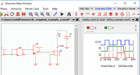
Deeds (Digital Circuit Simulator)
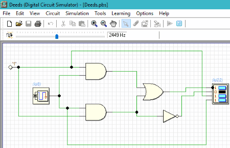
Deeds (Digital Circuit Simulator) is another advanced electronic circuit simulation software for Windows. Its almost like Digital Works, with all the components required for circuit design and circuit simulation. Along with basic logical and input/output components, there are various other components available, which are worth mentioning. These are: Decoders, Encoders, Multiplexers, ALUs, Memory devices, Registers, Counters, DACs, Micro computers, Bus, etc.
Simulate your circuit once designed, or test an already designed circuit. The simulation result shows on the output device of the circuit.
Supported file format is .pbs.
Бесплатные программы
Предоставляются пользователю в безвозмездное использование на постоянной основе. Они работают на соответствующих лицензиях. Поэтому, прежде чем начать использовать графические редакторы, необходимо скачать лицензию. Из популярных можно отметить Freeware, Open Source, GNU GPL, Public domain, Ad-supported и Donationware.
Программа для электросхем
Первая, третья и четвертая программы не ограничены по функционалу и могут быть применены в любое время суток. Вторая частично ограничена по коммерческой составляющей. Пятый сервис функционален и удобен. Шестой предоставляется безвозмездно, но создатель предлагает добровольно пожертвовать средства.
Функции бесплатного сервиса
VISIO
Редактор, которым просто и удобно управлять. Он имеет богатый функциональный набор. Несмотря на то, что приложение создано для показа информации на пк, сделанный документ можно в любое время распечатать для удобства.
VISIO
«Компас Электрик»
Приложение, сконструированное АСКОНом, помогающее проектировать любое электрооборудование и прикладывать к нему кондукторскую документацию. Платное программное обеспечение, но бесплатное на протяжении 2 месяцев.
«Компас Электрик»
ProfilCAD
Автоматизированное ПО, сконструированное для профессиональных электромонтажников и проектировщиков. Приложение помогает создавать электротехнический чертеж, отталкиваясь от плана помещения.
ProfilCAD
QElectroTech
Простой удобный и бесплатный сервис, созданный для формирования практических с электронными схемами-чертежами. Обычный редактор без специальных реализованных функций.
QElectroTech
123D Circuits
Веб-сервис, созданный для формирования проектов. Имеет в себе функции, нацеленные на программирование оборудования, симуляцию и трудовой анализ. Типовой функциональный набор имеет только радио-компоненты с модулями системы ардуино.
123D Circuits
Microsoft Visio
Приложение, отличающееся от других автоматическим и ручным расчетом принципиальной и силовой электрической схемы. Имеет в себе расширительный комплект базовых элементов. Нет возможности создания и редактирования объектов, доступен только их просмотр и распечатка.
Microsoft Visio
KiCad
Комплекс, имеющий открытый код. Система для сквозного конструирования электрических схем. Нацелена на разработку принципиальной схемы.
KiCad
CadSoft Eagle
Программное обеспечение в виде комплексной среды, где можно создать как принципиальные схемы, так и макеты плат. Работать с ней можно в любом режиме. Приложение платное, но для ознакомления предоставляется бесплатно.
Обратите внимание! Имеет в связи с бесплатным использованием функциональные ограничения. К примеру, работать в редакторе можно с одним файлом
CadSoft Eagle
MultiMedia Logic
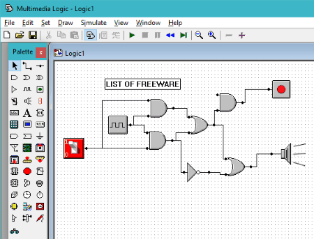
MultiMedia Logic can be another good option to design and simulate logical circuits. A large list of components will help you design extensive circuits. And, with the help of scope tools, you can analyze simulated circuit’s output.
The components to design circuit are available in a floating Tool Bar, and some extra components are available in the Draw menu. The components include Logic gates, Flip flops, Counters, ALUs, MUX, LEDs, Switches, and more. You can even attach the in-built oscilloscope to the designed circuit to view output waveform after simulation.
There’s nothing different in this logic circuit simulator as compared to above mentioned software, except a bit different layout.
Sensors, Transducers and Interactions with the External World
Electronic circuits don’t exist in isolation — most circuits have a purpose that involves interaction with the external world. In the simulation we’ve added some common types of input and output (e.g. switches and LEDs) but there are many types of transducers and we don’t model all of them. We are also not simulating all the physical effects that occur outside the electronic domain — e.g. how the load torque might vary as a motor moves a mechanism leading to changes to the motor’s electrical characteristics.
If you find you want to simulate a circuit with a type of transducer that isn’t in the model, e.g. a thermistor, you can just use an electrically equivalent component. So, for a thermistor just use a resistor and set it to different values to represent different temperatures. The sliders feature may be particularly useful for this purpose.
High Frequency Circuits
This simulator simulates the circuit using a series of short time steps. In each step the changes to the voltages and currents in the circuit are calculated based on the component models and the current circuit state. For this process to work the time steps used need to be significantly shorter than the duration of any event of interest in the circuit. Or, if you prefer, the time steps need to be significantly shorter than the period of the highest frequency signal of interest.
By default the simulator uses a 5µs step size. This is OK for audio frequency signals but not for radio frequency signals or fast digital signals. The step size can be changed from the «Other Options…» dialog on the options menu. For comparison, the transmission line example in the application uses a 5ps step size.
The step size shouldn’t be confused with the «Simulation Speed» controlled by the slider in the right hand panel. The step size controls how long (in simulated time) each step is. The «Simulation Speed» slider controls how often (in real time) the computer calculates a step.
Logical Circuit
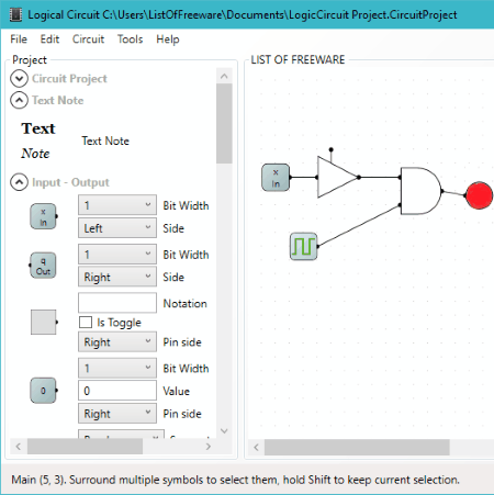
Logical Circuit is another opensource logical circuit simulation software that you may like. Like others, it lets you design and simulate circuit. But, what I liked about this software is that it lets you add parameters to components before adding to the circuit design board. While we are talking about components, let me inform you, that there are pretty basic but ample logical components available here. To name a few, you’ll find logical gates, input devices, output devices, sensor, clock, LED, 7 segment display, LED matrix, buzzer, probe, etc.
To simulate a circuit, simply press the Power button. An option lets you view the truth table of the designed circuit. Oscilloscope can also added to view output waveform.
A circuit can be saved as CircuitProject file to customize or view later.