Порты компьютера для подключения периферийных устройств, их виды и назначение
Содержание:
- Ограничения
- 7.9 Set IO Address & IRQ in the hardware (mostly for PnP)
- Свойство шины
- What is a virtual COM port?
- Properties
- Назначение
- 7.8 Choosing Addresses —Video card conflict with ttyS3
- 7.3 Common mistakes made re low-level configuring
- Назначение
- Почему интерфейс USB/RS, USB/KB, RS-232, KB нужно выбирать?
Ограничения
На практике в зависимости от качества применяемого кабеля требуемое расстояние передачи данных в 15 метров может не достигаться, составляя, к примеру, порядка 1,5 м на скорости 115200 бод для неэкранированного плоского или круглого кабеля. Это вызвано применением однофазных сигналов вместо дифференциальных, а также отсутствием требований по согласованию приёмника (и часто также передатчика) с линией.
Для преодоления этого ограничения, а также возможного получения гальванической развязки между узлами, преобразуют физический уровень RS-232 в другие физические уровни асинхронного интерфейса:
- «RS-232 — RS-422» (с сохранением полной программной совместимости) или «RS-232 — RS-485» (с определёнными программными ограничениями). Расстояние может быть увеличено до 1 км на скорости 9600 бод и при использовании кабеля типа «витая пара» категории 3;
- Внешний преобразователь «RS232 — Токовая петля» для 9-контактного разъёма, или соответствующие цепи 25-контактного разъёма, в случае наличия преобразователя внутри устройств.
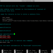
7.9 Set IO Address & IRQ in the hardware (mostly for PnP)
After it’s set in the hardware don’t forget to insure that it also
gets set in the driver by using . For non-PnP serial
ports they are either set in hardware by jumpers or by running a DOS
program («jumperless») to set them (it may disable PnP). The rest of
this subsection is only for PnP serial ports. Here’s a list of the
possible methods of configuring PnP serial ports:
- Using a PnP BIOS CMOS setup menu
(usually only for external
devices
on ttyS0 (Com1) and ttyS1 (Com2)) -
Letting a PnP BIOS automatically configure a PnP serial port
See - Doing nothing if the serial driver recognized your card OK
- Using for a PnP serial port non-PCI)
- Using setpci (pciutils or pcitools) for the PCI bus
The IO address and IRQ must be set (by PnP) in their registers each
time the system is powered on since PnP hardware doesn’t remember how
it was set when the power is shut off. A simple way to do this is to
let a PnP BIOS know that you don’t have a PnP OS and the BIOS will
automatically do this each time you start. This might cause problems
in Windows (which is a PnP OS) if you start Windows with the BIOS
thinking that Windows is not a PnP OS. See Plug-and-Play-HOWTO.
Plug-and-Play (PnP) was designed to automate this io-irq configuring,
but for Linux it initially made life much more complicated. In modern
Linux (2.4 kernels —partially in 2.2 kernels), each device driver has
to do it’s own PnP (using supplied software which it may utilize).
There is unfortunately no centralized planning for assigning IO
addresses and IRQs as there is in MS Windows. But it usually works
out OK in Linux anyway.
Using a PnP BIOS to I0-IRQ Configure
While the explanation of how to use setpci or isapnp for io-irq
configuring should come with such software, this is not the case if
you want to let a PnP BIOS do such configuring. Not all PnP BIOS can
do this. The BIOS usually has a CMOS menu for setting up the first
two serial ports. This menu may be hard to find. For an «Award»
BIOS it was found under «chipset features setup» There is often
little to choose from. Unless otherwise indicated in a menu, these
first two ports normally get set at the standard IO addresses and
IRQs. See
Whether you like it or not, when you start up a PC a PnP BIOS starts
to do PnP (io-irq) configuring of hardware devices. It may do the job
partially and turn the rest over to a PnP OS (which Linux is in some
sense) or if thinks you don’t have a PnP OS it may fully configure all
the PnP devices but not configure the device drivers. This is what
you want but it’s not always easy to figure out exactly what the PnP
BIOS has done.
If you tell the BIOS that you don’t have a PnP OS, then the PnP BIOS
should do the configuring of all PnP serial ports —not just the first
two. An indirect way to control what the BIOS does (if you have
Windows 9x on the same PC) is to «force» a configuration under
Windows. See Plug-and-Play-HOWTO and search for «forced». It’s
easier to use the CMOS BIOS menu which may override what you
«forced» under Windows. There could be a BIOS option that can set or
disable this «override» capability.
If you add a new PnP device, the BIOS should PnP configure it. It
could even change the io-irq of existing devices if required to avoid
any conflicts. For this purpose, it keeps a list of non-PnP devices
provided that you have told the BIOS how these non-PnP devices are
io-irq configured. One way to tell the BIOS this is by running a
program called ICU under DOS/Windows.
But how do you find out what the BIOS has done so that you set up the
device drivers with this info? The BIOS itself may provide some info,
either in its setup menus of via messages on the screen when you turn
on your computer. See
. Other ways of finding out is to use lspci for
the PCI bus or isapnp —dumpregs for the ISA bus. The cryptic results
it shows you may not be clear to a novice.
Свойство шины
Каждый интерфейс предъявляет свои требования к шине данных. В таких интерфейсах как UART может быть только два устройства (принимающее и отправляющее). При этом с точки зрения иерархии нет никакой разницы, оба устройства равнозначны. В интерфейсе SPI устройств может быть несколько, но только одно (на самом деле не всегда, но это исключение) является главным, т.е. ведущим или мастером (англ. master). Все остальные устройства являются ведомыми или подчинёнными (англ. slave). При этом SPI требует подводить к каждому устройству линию выбора (англ. chip select). Общение ведётся только с тем устройством, на линии которого присутствует сигнал активации.
Все ножки вышеописанных интерфейсов настраиваются как двухтактный выход. Но не все интерфейсы можно использовать подобным образом. Интерфейсы 1-Wire и I2C вместо линии выбора используют специальную команду с адресом устройства. Выгода очевидна — на линию можно повесить сколько угодно (есть ограничения) устройств, не вводя новые линии. Однако что будет, если два устройства захотят использовать шину одновременно? Непременно сложится ситуация, когда одно устройство подтянет линию к земле, а другое к питанию. Такое поведение, мягко говоря, не желательно и называется коротким замыканием (англ. short circuit).
Во избежание таких ситуаций, интерфейс требует, что бы: линия была подтянула внешним резистором к питанию, а устройства были настроены как вход с открытым стоком. Когда устройству нужно передать оно ничего не делает с линией, а когда нужно передать , оно подтягивает линию к земле. В таком случае, если произойдёт коллизия и два устройства одновременно начнут работать с линией, магический дым останется внутри микросхем.
What is a virtual COM port?
A virtual serial port is a special software package that emulates a physical COM interface in software, which allows you to add serial ports to your PC without using additional physical hardware like expansion cards, etc. A virtual COM port is a solution if there’s a lack of real serial ports in your system.
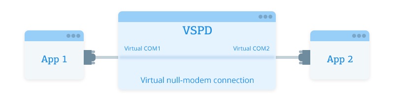
Now, thanks to some dedicated software (e.g. Virtual Serial Port Driver, Virtual Serial Over Ethernet, etc.), a remote serial device can be emulated on your local PC in such a way that you can communicate with it as though it were connected directly to your machine.
In this case, remote serial peripherals are accessed via a virtual COM port created in your local system by a specialized app. And all serial apps communicating with a remote peripheral over a virtual serial port recognize the interface as a hardware one.
This makes it possible to ensure compatibility between legacy serial software and modern equipment.
As for the way you manage your COM ports, it does not change significantly. Users still have to make the port configurations as they would do with a physical serial port. However, a modern COM port is no longer a bulky interface located on the back panel of the system unit but a completely software solution.
Properties
|
Возвращает базовый объект Stream для объекта SerialPort.Gets the underlying Stream object for a SerialPort object. |
|
|
Возвращает или задает скорость передачи для последовательного порта (в бодах).Gets or sets the serial baud rate. |
|
|
Получает или задает состояние сигнала разрыва.Gets or sets the break signal state. |
|
|
Возвращает число байтов данных, находящихся в буфере приема.Gets the number of bytes of data in the receive buffer. |
|
|
Получает число байтов данных, находящихся в буфере отправки.Gets the number of bytes of data in the send buffer. |
|
|
Возвращает значение, показывающее, может ли компонент вызывать событие.Gets a value indicating whether the component can raise an event. (Inherited from Component) |
|
|
Получает состояние линии обнаружения несущей для порта.Gets the state of the Carrier Detect line for the port. |
|
|
Возвращает объект IContainer, который содержит коллекцию Component.Gets the IContainer that contains the Component. (Inherited from Component) |
|
|
Возвращает состояние линии готовности к приему.Gets the state of the Clear-to-Send line. |
|
|
Возвращает или задает стандартное число битов данных в байте.Gets or sets the standard length of data bits per byte. |
|
|
Возвращает значение, указывающее, находится ли данный компонент Component в режиме конструктора в настоящее время.Gets a value that indicates whether the Component is currently in design mode. (Inherited from Component) |
|
|
Возвращает или задает значение, показывающее, игнорируются ли пустые байты (NULL), передаваемые между портом и буфером приема.Gets or sets a value indicating whether null bytes are ignored when transmitted between the port and the receive buffer. |
|
|
Получает или задает состояние сигнала готовности данных (DSR).Gets the state of the Data Set Ready (DSR) signal. |
|
|
Получает или задает значение, включающее поддержку сигнала готовности терминала (DTR) в сеансе последовательной связи.Gets or sets a value that enables the Data Terminal Ready (DTR) signal during serial communication. |
|
|
Получает или задает кодировку байтов для преобразования текста до и после передачи.Gets or sets the byte encoding for pre- and post-transmission conversion of text. |
|
|
Возвращает список обработчиков событий, которые прикреплены к этому объекту Component.Gets the list of event handlers that are attached to this Component. (Inherited from Component) |
|
|
Возвращает или задает протокол установления связи для передачи данных через последовательный порт с использованием значения Handshake.Gets or sets the handshaking protocol for serial port transmission of data using a value from Handshake. |
|
|
Возвращает значение, указывающее открытое или закрытое состояние объекта SerialPort.Gets a value indicating the open or closed status of the SerialPort object. |
|
|
Возвращает или задает значение, используемое для интерпретации окончания вызова методов и .Gets or sets the value used to interpret the end of a call to the and methods. |
|
|
Возвращает или задает протокол контроля четности.Gets or sets the parity-checking protocol. |
|
|
Возвращает или задает байт, которым заменяются недопустимые байты потока данных при обнаружении ошибок четности.Gets or sets the byte that replaces invalid bytes in a data stream when a parity error occurs. |
|
|
Получает или задает последовательный порт, в частности, любой из доступных портов COM.Gets or sets the port for communications, including but not limited to all available COM ports. |
|
|
Возвращает или задает размер входного буфера SerialPort.Gets or sets the size of the SerialPort input buffer. |
|
|
Получает или задает срок ожидания в миллисекундах для завершения операции чтения.Gets or sets the number of milliseconds before a time-out occurs when a read operation does not finish. |
|
|
Возвращает или задает число байтов во внутреннем входном буфере до возникновения события DataReceived.Gets or sets the number of bytes in the internal input buffer before a DataReceived event occurs. |
|
|
Возвращает или задает значение, показывающее, включен ли сигнал запроса передачи (RTS) в сеансе последовательной связи.Gets or sets a value indicating whether the Request to Send (RTS) signal is enabled during serial communication. |
|
|
Возвращает или задает ISite объекта Component.Gets or sets the ISite of the Component. (Inherited from Component) |
|
|
Получает или задает стандартное число стоповых битов в байте.Gets or sets the standard number of stopbits per byte. |
|
|
Возвращает или задает размер выходного буфера последовательного порта.Gets or sets the size of the serial port output buffer. |
|
|
Получает или задает срок ожидания в миллисекундах для завершения операции записи.Gets or sets the number of milliseconds before a time-out occurs when a write operation does not finish. |
Назначение
Наиболее часто для последовательного порта персональных компьютеров используется стандарт RS-232C. Ранее последовательный порт использовался для подключения терминала, позже для модема или мыши. Сейчас он используется для соединения с источниками бесперебойного питания, для связи с аппаратными средствами разработки встраиваемых вычислительных систем, спутниковыми ресиверами, кассовыми аппаратами, программаторами, с приборами систем безопасности объектов, а также с многими прочими устройствами.
С помощью COM-порта можно соединить два компьютера, используя так называемый «нуль-модемный кабель» (см. ниже). Такой кабель использовался со времен MS-DOS для передачи файлов с одного компьютера на другой, в UNIX для терминального доступа к другой машине, а в Windows (даже современной) — для отладчика уровня ядра.
Достоинством технологии является крайняя простота оборудования. Недостатком является низкая скорость, крупные разъёмы, а также зачастую высокие требования ко времени отклика ОС и драйвера и большое количество прерываний (одно на половину аппаратной очереди, то есть 8 байт).
7.8 Choosing Addresses —Video card conflict with ttyS3
Here’s a problem with some old serial cards. The IO address of
the IBM 8514 video board (and others like it) is allegedly 0x?2e8
where ? is 2, 4, 8, or 9. This may conflict with the IO address of
at 0x02e8. Your may think that this shouldn’t happen since
the addresses are different in the high order digit (the leading 0 in
02e8). You’re right, but a poorly designed serial port may ignore the
high order digit and respond to any address that ends in 2e8. That is
bad news if you try to use (ISA bus) at this IO address.
For the ISA bus you should try to use the default addresses shown
below. PCI cards use different addresses so as not to conflict with
ISA addresses. The addresses shown below represent the first address
of an 8-byte range. For example 3f8 is really the range 3f8-3ff.
Each serial device (as well as other types of devices that use IO
addresses) needs its own unique address range. There should be no
overlaps (conflicts). Here are the default addresses for commonly
used serial ports on the ISA bus:
Suppose there is an address conflict (as reported by ) between a real serial port and another port which
does not physically exist (and shows UART: unknown). Such a conflict
shouldn’t cause problems but it sometimes does in older kernels. To
avoid this problem don’t permit such address conflicts or delete
/dev/ttySx if it doesn’t physically exist.
7.3 Common mistakes made re low-level configuring
Here are some common mistakes people make:
- setserial command: They run it (without the «autoconfig» and
auto_irq options) and think it has checked the hardware to see if
what it shows is correct (it hasn’t). - setserial messages: They see them displayed on the screen at
boot-time (or by giving the setserial command) and erroneously think
that the result always shows how their hardware is actually
configured. - /proc/interrupts: When their serial device isn’t in use they
don’t see its interrupt there, and erroneously conclude that their
serial port can’t be found (or doesn’t have an interrupt set). - /proc/ioports and /proc/tty/driver/serial: People think this
shows the actual hardware configuration when it only shows about the
same info (possibly erroneous) as setserial.
Назначение
Изначально создавался для подключения телефонных модемов к компьютерам[источник?]. В связи с такой специализацией имеет рудименты в виде, например, отдельной линии RING («звонок»). Постепенно телефонные модемы перешли на другие интерфейсы (USB), но разъём для RS-232 имелся на всех персональных компьютерах и многие изготовители оборудования использовали его для подключения своего оборудования. Например, компьютерные мышки.
В настоящее время чаще всего используется в промышленном и узкоспециальном оборудовании, встраиваемых устройствах. На портативных компьютерах (ноутбуках, нетбуках, КПК и т. п.) широкого применения RS-232 не нашел, однако материнские платы стационарных персональных компьютеров обычно ещё содержат RS-232 — либо в виде разъёма на задней панели, либо в виде колодки для подключения шлейфа на плате. Также возможно использование переходников-преобразователей.
Также этот стандарт используется для взаимодействия микроконтроллеров различных архитектур, имеющими в своем составе интерфейс UART, с другими цифровыми устройствами и периферией.
Почему интерфейс USB/RS, USB/KB, RS-232, KB нужно выбирать?
Действительно, какая разница, какой интерфейс поставляется с
устройством? На корпусе системного блока pos-системы имеются
разъемы для подключения сканера штрих-кода, фискального
регистратора, принтера этикеток, дисплея покупателя,
программируемой клавиатуры, считывателя магнитных или RFID карт.
Различные модели pos-компьютеров оснащены (как правило, на задней и
передней панелях) различным количеством и различными типами
разъемов. Доукомплектовывая pos-систему, скажем, сканером штрих
кодов, нужно планировать его подключение таким образом, чтобы
- обеспечить совместимость его интерфейса с интерфейсом
системного блока, - обеспечить возможность поддержки интерфейса программным
обеспечением, - учесть планы по дальнейшей модернизации/расширению
pos-системы.