Пошаговая прошивка openwrt на роутер tp-link tl-wr741nd
Содержание:
Конфигурация
Показанная конфигурация заменяет “интерфейс” WAN, поэтому нет необходимости редактировать настройки firewall и пр. Заметьте, что если вы хотите оставить штатный интерфейс WAN, то Вам придётся обозначить новый как WAN2 (или как-то иначе, чтобы Вам было понятно) и сделать соответствующие изменения в брандмауэре.
Настраиваем сеть
config interface wan
        option ifname  ppp0
        option pincode 1234
        option device  devttyUSB0
        option apn     your.apn
        option service umts
        option proto   3g
Заменяем ‘pincode’ на корректный пинкод SIM-карты. Замечание! Если на СИМ-карте отключена проверка пинкода, то могут возникнуть проблеммы, обязательно активируйте проверку пинкода СИМ-карты.
Если вы подключаетесь через телефон, то необходимости проверять пин код нет, так как он был проверен при включении телфона
Замените ‘device’ на правильный USB port вашего модема. на телфонах скорей всего будет /dev/ttyACM0.
Замените ‘apn’ на корректный APN вашего 3g/umts провайдера.
Все операторы России требует авторизации пользователя, поэтому добавляем еще 2 строчки
        option username yourusername
        option password yourpassword
заменяем ‘username’ и ‘password’ на правильный. Если у вас нет информации (apn, username и password) Вам прямая дорога в mobile-broadband-provider-info database .
| : Автор перевода статьи не понял о какой функции идет речь. Пожалуйста поправьте строчки ниже и добавьте комментариев. |
For some providers, apperently it is neccessary to add ‘noipdefault’ to ‘pppd_options’. If logread shows that the connection was established and CHAP authentication was successful, but the connection was immediately dropped after, then try:
option 'pppd_options' 'noipdefault'
If your provider supports PAP authentication only then you need to disable all other protocols via these added options:
option 'pppd_options' 'noipdefault refuse-chap refuse-mschap refuse-mschap-v2 refuse-eap'
Поздравляю!!! Вы настроили сетевой интерфейс.
Настройка Chat
Теперь нам нужно проверить работает chatscript, или нет с нашим провайдером.
Находим файл ‘/etc/chatscripts/3g.chat’, и смотрим, что там написано:
ABORT   BUSY
ABORT   'NO CARRIER'
ABORT   ERROR
REPORT  CONNECT
TIMEOUT 12
""      "AT&F"
OK      "ATE1"
OK      'AT+CGDCONT=1,"IP","$USE_APN"'
ABORT   'NO CARRIER'
TIMEOUT 15
OK      "ATD*99***1#"
CONNECT ' '
Если вашему модему нужны специфичныые АТ команды, Вы можете добавить их в этот список. Так же вы можете отредактировать телефон дозвона (в большинстве модемов GPRS, EDGE и 3G достаточно просто *99#).
Hardware Highlights
| Model | ↓ Version | SoC | CPU MHz | Flash MB | RAM MB | WLAN Hardware | WLAN2.4 | WLAN5.0 | 100M ports | Gbit ports | Modem | USB |
|---|---|---|---|---|---|---|---|---|---|---|---|---|
| TL-WR740N | v1 | Atheros AR7240 | 400 | 4 | 32 | Atheros AR92xx | b/g/n | — | 5 | — | — | Mod |
| TL-WR740N | v2.1 (BR) | Atheros AR7240 | 400 | 2 | 32 | ¿ | b/g/n | — | 5 | — | — | — |
| TL-WR740N | v3 | Atheros AR7240 | 400 | 4 | 32 | Atheros AR92xx | b/g/n | — | 5 | — | — | Mod |
| TL-WR740N | v4.20, v4.21, v4.22, v4.25, v4.26, v4.27, v4.28 | Atheros AR9331 | 400 | 4 | 32 | Atheros AR9331 | b/g/n | — | 5 | — | — | — |
| TL-WR740N | v4.23, v4.24 | Atheros AR9330 rev 1 | 400 | 4 | 32 | Atheros AR9330 rev 1 | b/g/n | — | 5 | — | — | — |
| TL-WR740N | v5 (EU) | Atheros AR9331 | 400 | 4 | 32 | ¿ | b/g/n | — | 5 | — | — | — |
| TL-WR740N | v5.1 (UA) | Atheros AR9331-AL3A | 400 | 4 | 32 | ¿ | b/g/n | ¿ | 5 | — | — | — |
| TL-WR740N | v6 | Qualcomm Atheros QCA9533 | 560 | 4 | 32 | Qualcomm Atheros QCA9533 | b/g/n | — | 5 | — | — | — |
Flash/Recovery (v2)
Using the integrated tftp capability of the router.
- Turn off the router.
- Connect pc to one of the router LAN ports.
- Set your PC IPv4 address to .
- Run any TFTP server on the PC.
-
Put the recovery firmware on the root directory of TFTP server and name the file
-
Start the router by pressing power button while holding the WPS/Reset button (or both WPS/Reset and WIFI buttons)
- Router connects to your PC with IPv4 address , downloads the firmware, installs it and reboots. LEDs are flashing. Now you have OpenWrt installed.
- Change your IPv4 PC address to something in network or use DHCP to get an address from your OpenWrt router.
- Done! You can login to your router via ssh.
Serial console
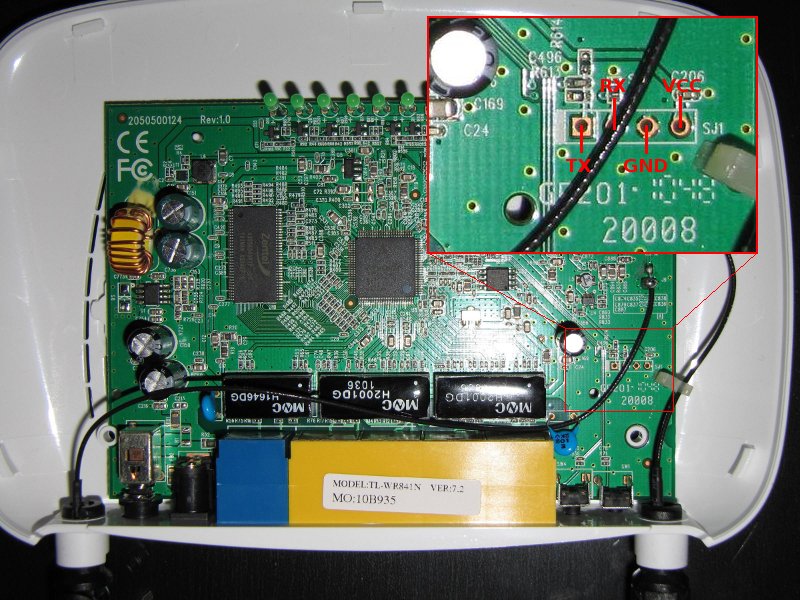
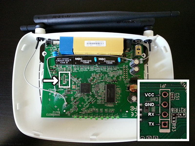
Getting serial console is pretty standard fare. You need a MAX323 or similar level-shifter. The pinout on the router is RX — TX — GND — +5V (Power connector).
If you do not have serial port on your PC, use Nokia CA-42 data USB cable.
- TP-Link WR841ND V7.0: The 10k the pullup resistor is not required, connect all four pins (tested with 1a86:7523 QinHeng Electronics HL-340 USB-Serial adapter, make sure to set its voltage to 3V not 5V)
- TP-Link WR841ND V7.1: Also requires the 10k pullup resistor between TX and the 3.3V pin. Without the resistor I just get garbage when I type, but can see some console output.
- TP-LINK WR841ND V7.2: Power conector (+5V) is ignored, just connect RX — TX — GND and router power cord, work fine…
-
TP-LINK WR841ND V7.2: Has a VCC of +3.3V and like the TL-MR3420 needed to connect a 10k pullup resistor between the TX and the 3.3V pin to get reliable serial:
-
TP-Link TL-WR841ND v8.4: was not required 10K resistor. My TTL to RS232 converter has bad marking of Tx and Rx pins. So, it was necessary to connect Tx-Tx and Rx-Rx. The connection of Vcc (3.3V) was necessary too. The connection scheme you can find on the following image:
{media:tplink:tl-wr841:tl-wr841nd-v8.4_serial.jpg?400|}} - TP-Link TL841N v9.0: I had to remove R26. It’s a pull-up between RX (device side) and VCC. My FTDI device couldn’t send data with R26 attached.
- TP-Link TL-WR841N V9.2: Works fine without removing R26, just normal TX,RX,GND connection works fine.
- TP-Link TL-WR841N v10: Seems to be the same PCB like the version v9. Serial works after remove R26, see v9.0. Tested with CH340G USB/serial device.
- just swap TX and GND pin in serial and no garbage in serial console, but this is read-only.
Tip: Connecting TL-WR841N v8.1 via Arduino Due R3 ( forum link):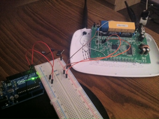
Serial port settings
| Version | v3.2 | v5 | v7.X | v8.4 | v9.0 / v10.0 | v11.1 / v12.0 |
|---|---|---|---|---|---|---|
| Image | 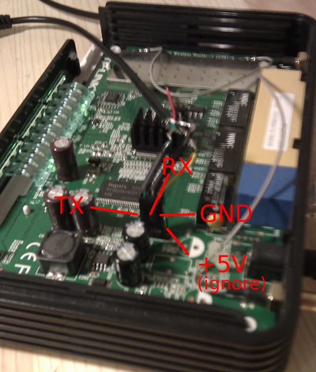 |
 |
 |
 |
||
| U-Boot speed | 9600 | 115200 | ||||
| kernel speed | 115200 — switch automaticaly | 115200 | ||||
| Data format | always 8N1 |
After connecting, you will be greeted by something like this:
AP93 (ar7240) U-boot
DRAM:
sri
#### TAP VALUE 1 = 9, 2 = 9
32 MB
id read 0x100000ff
flash size 4194304, sector count = 64
Flash:  4 MB
Using default environment

In:    serial
Out:   serial
Err:   serial
Net:   ag7240_enet_initialize...
No valid address in Flash. Using fixed address
: cfg1 0xf cfg2 0x7014
eth0: 00:03:7f:09:0b:ad
eth0 up
No valid address in Flash. Using fixed address
: cfg1 0xf cfg2 0x7214
eth1: 00:03:7f:09:0b:ad
ATHRS26: resetting s26
ATHRS26: s26 reset done
eth1 up
eth0, eth1
Autobooting in 1 seconds
You now have one second to enter “tpl” (without the quotes) to get to the Uboot console prompt.
VPN клиент на OpenWrt
- Подробности
- Категория: Настройка
- Опубликовано: 11 ноября 2018
- Просмотров: 29017
 Использовать VPN для доступа к запрещенным сайтам сейчас уже не кажется таким кощунством, как раньше. За последние лет десять было создано такое огромное количество VPN-сервисов, который все в один голос трубят, как снимают с вас ограничения на интернет-контент, наложенный как нашим государством, так и отдельными интернет-провайдерами в частности, и о том, как все супер-анонимно и абсолютно бесследно. Так ли это на самом деле, каждый решает для себя сам. Мы же рассмотрим сегодня как поднять VPN клиента на вашем OpenWrt роутере. В качестве примера будем устанавливать VPN-соединение на устройстве TP-Link WR842ND с OpenWrt 18.06.1 используя пакет OpenVPN и VPN сервис FrootVPN.
Hardware
| Version | v3 | v5 | v7 | v8 | v9 | v10 | v11 | v12 | v13 | v14 |
|---|---|---|---|---|---|---|---|---|---|---|
| Instruction set: | MIPS | |||||||||
| Vendor: | Atheros | MediaTek | ||||||||
| bootloader: | uboot | |||||||||
| System-On-Chip: | AR9130 | AR7240 rev 2 | AR7241-AH1A | AR9341 | QCA9533-AL3A | QCA9533-BL3A | QCA9533-AL3A | MT7628NN | ||
| cpu Frq: | 400 MHz | 535 MHz | 550 MHz | 650 MHz | 575 MHz | |||||
| BogoMIPS: | 265.42 | 265.42 | 265.42 | 266.64 | 366.18 | 432.53 | 385.84 | 385.84 | ||
| Flash-Chip: | ST 25P32V6P | Hynix | Eon EN25F32-100HIP | Spansion FL032PIF | Winbond 25Q32FVS1G | Spansion FL032PIF | GigaDevice 25Q64CSIG | GigaDevice 25Q32CSIG | ||
| Flash size: | 4 MiB | 8 MiB | 4 MiB | |||||||
| RAM-Chip: | Hynix HY5DU561622FTP-5 | Zentel A3S56D40ETP-G5 | ESMT M13S2561616A-5T | Winbond W9425G6JH-5 | Zentel A3S56D40GTP-50 | Zentel A3S56D40GTP-50L | ESMT M14D5121632A -2.5B / Winbond W9751G6KB-25 | Zentel A3S56D40GTP-50L | ||
| RAM size: | 32 MiB | 64 MiB | 32 MiB | |||||||
| Wireless: | Atheros AR9100 Rev:7 | Atheros AR9280 Rev:2 | Atheros AR9287-BL1A 2.4GHz 802.11bgn | AR9341 | QCA9533-AL3A | QCA9533-BL3A | QCA9533-AL3A | MT7628NN | ||
| switch: | Marvell 88E6060 | AR7240 built-in | AR7241 built-in | AR9341 built-in | QCA9533-AL3A built-in | QCA9533-BL3A built-in | MT7628NN built-in | |||
| USB: | No | No | No | |||||||
| Serial: | Yes | |||||||||
| JTAG: | Yes | No |
Supported Versions
| Brand | Model | Version | Current Release | OEM Info | Forum Topic | Technical Data |
|---|---|---|---|---|---|---|
| TP-Link | TL-WR741ND | 1, 1.8 | 18.06.8 | View/Edit data | ||
| TP-Link | TL-WR741ND | 1.4, 1.5, 1.9, 3 | 18.06.2 | View/Edit data | ||
| TP-Link | TL-WR741ND | v5 | 18.06.8 | View/Edit data | ||
| TP-Link | TL-WR741ND | v2 | 18.06.8 | View/Edit data | ||
| TP-Link | TL-WR741ND | v4.x | 18.06.8 | View/Edit data |
For clarity and ease of use we should consider trimming below list. I have rebooted the which should help clearing the duplicates. For example, judging from the details available at WikiDevi, the v1.6 and v1.9 seem already identical. The fact OpenWrt images only cover major updates (ie v1, v2, v4) should be a further indicator. – Bernini 2015-01-06
| Model Version | Launch Date | OpenWrt Supported Since | Model Specific Notes |
|---|---|---|---|
| v1.x | — | Backfire 10.03.1 | v1.9 has a different flash chip compared to other v1.x models, see SVN r23712 and related ticket. |
| v2 | — | Backfire 10.03.1 | Tested with r29614, working correctly. |
| v2.1 | — | trunk (r27195) | notes |
| v2.3 | — | trunk (r28601) | Tested Backfire revision 28601 |
| v2.4 | — | Attitude Adjustment 12.09 | Rounded chassis (box branded WR740N). Also works without issues with CC 15.05.1 release |
| v3 | 2011-08 | ? | WikiDevi only knows a v3.1, no v3. Confirms OpenWrt support though. |
| v3.1 (CN) | — | ? | suggests support, but user hacked a v1 OpenWrt image to test. |
| v4 | 2011-09 | Attitude Adjustment 12.09 | AR9331 chipset. |
| v4.20 | 2012-04 | Attitude Adjustment 12.09 | Working as of trunk r31273, note 4.20 is newer than 4.3. |
| v4.3 | — | Attitude Adjustment 12.09 | Working as of trunk r31249, hardware reports “TP-LINK TL-WR741ND v4”. |
| v5.0 | — | trunk (r46238) | See: SVN r46236 and ; |
Upgrading OpenWrt
→ generic.sysupgrade
These are generic instructions. Update with your router’s specifics.
Terminal Upgrade Process
If you don’t have a GUI (LuCI) available, you can alternatively upgrade via the command line.
There are two command line methods for upgrading:
Note: It is important that you put the firmware image into the ramdisk (/tmp) before you start flashing.
sysupgrade
Login as root via SSH on 192.168.1.1, then enter the following commands:
cd /tmp
wget http://downloads.openwrt.org/snapshots/trunk/XXX/xxx.abc
sysupgrade /tmp/xxx.abc
mtd
If does not support this router, use .
Login as root via SSH on 192.168.1.1, then enter the following commands:
cd /tmp
wget http://downloads.openwrt.org/snapshots/trunk/XXX/xxx.abc
mtd write /tmp/xxx.abc linux && reboot
Introduction
The second half of this page (specific device recommendations) is very outdated.
Users should consider multi-core, ARM-based (or x86_64/AMD64) devices for mid-range and higher applications.
Purchase of a device with less than 16 MB of flash or less than 128 MB or RAM is unwise at this time (2019).
A device with two, “ath10k” radios should have at least 256 MB of RAM. This eliminates the Asus RT-AC58U, RT-ACRH13, and similar.
Really specific per scenario but these are generic recommendations based upon what’s considered “reasonable” in terms of reliability and performance. Please note that the OpenWrt project itself does not endorse any hardware or manufacturer unless there’s a public statement, this is solely a list put together by the community. General recommendations are at least 16 Mbyte of flash and 128 Mbyte of RAM.
Note that some manufacturers claim “32 mb flash” or the like (small “b”) – this is 32 Mbits, or only 4 MBytes.
Platforms that have less than 16 Mbyte of flash will have noticeable space constraints. Having less than 128 Mbyte of RAM also imposes limitations, basic network functionality may work however there are reports of memory errors while using opkg and luci among other services which may operate unreliable or in worst case freeze the system. Support for either 4 MB of flash or 32 MB of RAM has already been discontinued, due to the size of the Linux kernel and run-time footprint of the third-party software required for a basic, running OpenWrt system. One should expect that 64 MB RAM will be unsupportable in the near future, as well as support for 8 MB of flash.
A device with two, “ath10k” radios should have at least 256 MB of RAM for stable operation. This eliminates the Asus RT-AC58U, RT-ACRH13, and similar.
For many opinions, see the OpenWrt Forum. For example https://forum.openwrt.org/search?q=favorite%20device
Are «Snapshot» Devices Supported?
Yes, devices are supported by OpenWrt “snapshots” until a formal release includes the device.
In many cases, a newer device (or one that has recently had OpenWrt ported to it) will only be available as a snapshot build for months (or even over a year) before a formal release includes it. Snapshot (or ) builds and code are not necessarily “less stable” than “release” builds. In many cases the snapshot build will outperform a release build, or resolve issues found in the release builds.
The main challenge for many users with snapshot builds are that they don’t come with LuCI (GUI) preinstalled, and many “special” packages a user wants to add generally need to be flashed when the ROM is downloaded and flashed. Getting LuCI up and running is easily resolved with an Internet connection, SSH client, and a couple of simple commands.
See further Development builds / snapshots
Installation
| Model | ↓ Version | Current Release | Firmware OpenWrt Install | Firmware OpenWrt Upgrade | Firmware OEM Stock |
|---|---|---|---|---|---|
| TL-WR940N | v1 | 18.06.8 | |||
| TL-WR940N | v2 | 18.06.8 | |||
| TL-WR940N | v3 | 18.06.8 | |||
| TL-WR940N | v4 | 18.06.8 | |||
| TL-WR940N | v5 | 18.06.8 | |||
| TL-WR940N | v6 | 18.06.8 |
→ Install OpenWrt (generic explanation)
For installation see TP-Link TL-WR941ND.
Recovery information
- Rename any of the Stock/OpenWrt/LEDE factory file to wr941ndv6_tp_recovery.bin
- Set IP of computer to 192.168.0.66
- On v6.1 devices, it’s very likely there will have to be a switch between the machine running the TFTP server (dnsmasq works well) and the router (also see https://forum.openwrt.org/t/tp-link-tl-wr940n-eu-v6-1-is-it-supported/29774/23)
- Start TFTP server
- Start the router with the set button held down.
- Wait until the LED changes color, then release the reset button
- The TFTP server should log the firmware file having been downloaded — if not, just keep trying
-
Once the file has been downloaded successfully, give it a minute or too, then try to get an IP address via DHCP
- In case TFTP does not work, you’ll have to attach a serial cable (see below). Serial login for stock firmware: root:sohoadmin
Bootloader Mods
- you could read about bootloader in general and about Das U-Boot in particular.
U-Boot 1.1.4 modification for routers
Forum member pepe2k made a modification of U-Boot 1.1.4 for Qualcomm Atheros SoCs based devices (the project is still being developed, so new devices and SoCs will be supported in the future). Up to date information, sources can be found on official GitHub repository and binary images here.
This modification started from wr703n-uboot-with-web-failsafe project, but supports more devices, all modern web browsers, has a lot of improvements and other modifications (like U-Boot NetConsole, custom commands, overclocking possibilities etc.).
More information:
-
Official repository on GitHub: U-Boot 1.1.4 modification for routers
-
Binary images
-
Discussion about this project on OpenWrt forum
-
An article (in Polish) about one of the first version of this project on www.tech-blog.pl
Hardware Mods
USB 1.1 Port
Tested on WR841n_v5.1
Attention. Firmware of TP-Link TL-MR 3420 is coming to WR841ND v7.2 — verified. (OpenWrt Firmware Attitude Adjustment (r28380) / LuCI Trunk (trunk+svn7612))
But working usb port has not been verified. Probably enough to use this firmware, but do not compile a new one 🙂
Overview of the board:
Soldering (wire with red accent means D+). R185 and R183 can be shorted then D+/D- will appear in J1.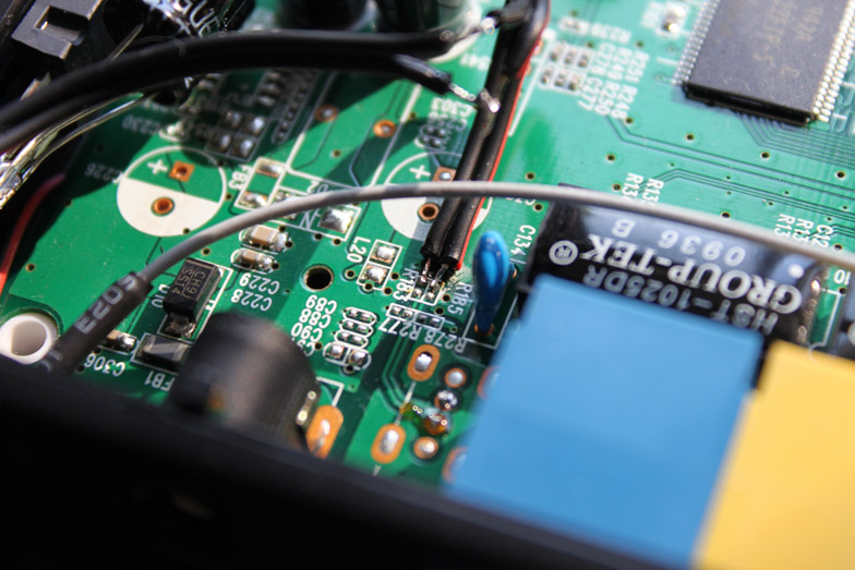
To get working USB the new firmware build is required. Files to edit are listed below:
1. Edit file target/linux/ar71xx/files/arch/mips/ar71xx/mach-tl-wr841nd.c
    Add line #include "dev-usb.h" after line #include "dev-leds-gpio.h"
    Add line ar71xx_add_device_usb(); before line ar71xx_add_device_mdio(0x0);
2. Edit file target/linux/ar71xx/files/arch/mips/ar71xx/setup.c
Add line ar71xx_pll_wr(0x08, 0x00001030); before line ar71xx_detect_mem_size();
3. Edit file target/linux/ar71xx/files/arch/mips/ar71xx/Kconfig:
config AR71XX_MACH_TL_WR841N_V1
        bool "TP-LINK TL-WR841N v1 support"
        select AR71XX_DEV_M25P80
        select AR71XX_DEV_PB42_PCI if PCI
        select AR71XX_DEV_DSA
        select AR71XX_DEV_GPIO_BUTTONS
        select AR71XX_DEV_LEDS_GPIO
        select AR71XX_DEV_USB
        default n
For newer version of trunk (as of 2013 March)
1.Edit file target/linux/ar71xx/files/arch/mips/ath79/mach-tl-wr841n.c
    Add line #include "dev-usb.h" after line #include "dev-leds-gpio.h"
    Add line ath79_register_usb(); after line ath79_register_eth(0);
2. Edit file target/linux/ar71xx/generic/profiles/tp-link.mk, add packages in the definition of TLWR841 as following.
define Profile/TLWR841
	NAME:=TP-LINK TL-WR841N/ND
	PACKAGES:=kmod-usb-core kmod-usb2 kmod-ledtrig-usbdev
endef
i.e L7805 with 470uF and 100uF can be used to obtain 5V from the stock power supply.
NOTE: in case of v5.1 sections for WR741N instead of WR841N_V1 have to be edited (Kconfig, mach-tl-wr741nd.c).
USB 2.0 Port on v7
tested with WR841 v7.1 and trunk revision 30430. New patch for rev. 32461 available
Hardware mod is on pictures, nothing changed.
External Link
Kernel mod is different, because new kernel version is released in revision 30430.
Here is patch for kernel 3.3: http://mysicka.ics.muni.cz/openwrt/usb-patch-final.patch
Apply this patch and build…
USB 2.0 Port on v8
I haven’t tested this, but it appears to show where the USB D+ and D- pins can be found on the AR9341: http://ge.tt/m/2IKNi5l/
16M Flash & 64M RAM on v8 (China)
v8 (China) uses EON 2M flash, replace with Winbond W25Q128FVSG
Original RAM chip 16M ZENTEL A3S28D40FTP, replace RAM chip Hynix HY5DU121622DTP 64M (DDR)
updated v8 firmware successfully
Hardware info:
| CPU | Atheros AR9341 rev 1 |
| Memory | 64MB DDR |
| Flash | Winbond W25Q128 @ 20MHz (16MB) |
| ETH | Atheros AR8228/AR8229 rev 1 |
| Clock | CPU: 560MHz, DDR: 400MHz, AHB: 200MHz, Ref: 25MHz |
NOTE: ART partition can be extracted from original flash (EON 2M) at last 64K area, address as 0x1F0000. ART data need to be appended to new flash manually, otherwise an ar934x_wmac error occurs without wifi function.
64MB RAM Mod v7
Working chips:
- Hynix HY5DU121622DTP-D43 (From Mustang DDR SO-DIMM 512 MB)
- Hynix HY5DU121622CTP-D43 (From Hynix DDR SO-DIMM PC2700S-25330 512MB DDR 333MHz CL 2.5
- Hynix HY5DU121622AT-J (From DDR 256MB PC400 (BUD968RA))
- Infineon HYB25D512160BE (From Infineon DDR SO-DIMM 512 MB)
- Elpida EDD5116ADTA-6B-E (From Elpida DDR SO-DIMM 512 MB)
- Elpida EDD5116AFTA-5B-E (From Elpida DDR SO-DIMM 512 MB)
- Samsung K4H511638C-UCB3 (From Samsung DDR SO-DIMM 512 MB)
Hardware
Info
| Architecture: | MIPS |
| Vendor: | Qualcomm Atheros |
| bootloader: | U-Boot |
| System-On-Chip: | AR7242 |
| CPU/Speed | 400 Mhz |
| Flash-Chip: | Spansion FL064PIF |
| Flash size: | 8192 KiB |
| RAM: | Zentel A4S12D40FTP-G5 64 MiB |
| Wireless: | Atheros AR9380 Dual-Band 450Mbps 3×3 ABGN |
| Ethernet: | RTL8367R |
| Internet: | n/a |
| USB: | Yes 1 x 2.0 |
| Serial: | Yes |
| JTAG: | ??? |
Performance
With Openwrt, this device can handle just over 300Mbps sustained UDP throughput at maximum link rate (450Mbps) and about 190Mbps sustained TCP throughput wirelessly with encryption off. With encryption on, maximum UDP throughput drops to about 270Mbps. WAN to LAN throughput with the same Openwrt build tops out at about 235Mbps. WAN to LAN with the stock firmware is dire, topping out at about 80-100Mbps, so Openwrt gives over double the routing speed.
Photos
v1.2
Note: Despite having the space and markings for a metal shield over the wireless radio, it is not included on most units.
Serial Port
Serial port on this model was easy to figure out. I simply used a multimeter to check for ground, and +3.3vdc, then tried the other two pins, reversing until I/O was achieved. You will require a TTL/Serial adapter (CP21xx or PL2303) in order to convert the UART TTL voltages to PC voltages, otherwise you risk damaging your router and/or serial port.
In the picture below I soldered a 4-pin connector onto my device (at a slight angle to facilitate re-closure of the case). There are no pull-up resistors or shorts to make on this device. Simply hook onto the Ground, RX and TX, and you’re laughing.

Note: DO NOT CONNECT the 3.3vdc to your USB/TTL device. As you can see in the picture, I left that pin off at the header.
Opening/closing the case
1. Remove the (4) adhesive rubber feet
2. Unscrew the (4) phillips screws
3. Use a spudger or common tip screwdriver to gently pry a corner of the top until you hear a click.
4. Follow around the seam with your spudger until you unhinge all the latches and the top will come off easily.
Simply reverse the process to reinstall the cover.
Recovery
You will need:
1. Serial cable with a 3.3v converter. Those nokia cables work well.
2. A terminal emulation. I used putty on windows, minicom on linux.
3. A TFTP server. I used tftp-hpa under linux.
4. A PC with a static IP address of 192.168.1.27 netmask 255.255.255.0. Please take note that I do not know if that address work on all routers. Mine is what it was looking for.
5. A network cable between the computer and the router (any) lan port.
How to recover:
1. Connect the serial cable.
2. Open a terminal with 115200 8n1.
4. Wait for “Autobooting in 1 seconds”, then quickly type “tpl” (without the quotes) within the 1 second timeout. Power cycle if you miss it. You should be welcomed with “ar7240>”. You are now talking to the bootloader. If nothing happend within a few seconds, check your connections.
5. Erase the flash: erase 0x9f020000 +7c0000
6. Transfert the firmware to ram, use the squashfs factory one: tftpboot 0x81000000 code.bin. If it timeout, verify which address the router want to fetch the file from. Mine wanted from 192.168.1.27 and I do not know if this is universal or “random”.
7. Copy from ram to flash: cp.b 0x81000000 0x9f020000 0x7c0000
8. Boot the new firmware: bootm 0x9f020000
A note on the address:
1. 0x81000000 is the default memory address that tftpboot wanted to use.
2. 0x9f020000 is the flash base address. Obtained from the serial console log when it tried to boot from the line: “## Booting image at 9f020000 …”
3. 0x7c0000 is the firmware size.
Back to Original Firmware
1. Download the original firmware from the tp-link website
2. Cut the file:
dd if=orig.bin of=tplink.bin skip=257 bs=512
3. Write to flash:
mtd -r write /tmp/tplink.bin firmware
GPIOs
| Name | Purpose | Pin |
|---|---|---|
| gpio0 | LED10 | 107 |
| gpio1 | LED11 | 84 |
| gpio3 | SPI_SI | 76 |
| gpio4 | SPI_SCK | 77 |
| gpio9 | R172 not assembled | 86 |
| gpio12 | SW1 | 89 |
Basic configuration
With BARRIER BREAKER (Bleeding Edge, r40867)
Tested with the wr841n v9 with or better . The system supports multiple virtual access points.
Modify the files that follows according to your needs (and, in the case, search for the file definition here in the wiki to understand how it works)
etc/config/wireless
config wifi-device  radio0
        option type     mac80211
        option channel  9 #same channel of the existing wifi network
        option path     'platform/qca953x_wmac'
        option txpower  12 #this depends on your needs, default is 20 dBm. Lower it is healthier (citation needed)
        # REMOVE THIS LINE TO ENABLE WIFI:
        #option disabled 1

config wifi-iface
        option device   radio0
        option network  lan
        option mode     ap
        option ssid     'This_is_a_new_wifi_network'
        option encryption       psk2 #wpa2 psk
        option key      'this_is_the_wifi_password'

config wifi-iface
        option device   radio0
        option network  wan
        option mode     'sta'
        option ssid     'This_is_the_name_of_the_existing_wifi_network'
        option encryption       psk2
        option key      'this_is_the_wifi_password_to_get_the_connection'
etc/config/network
config interface 'loopback'
        option ifname 'lo'
        option proto 'static'
        option ipaddr '127.0.0.1'
        option netmask '255.0.0.0'

config globals 'globals'
        option ula_prefix 'here is written something, no need to modify it'

config interface 'lan'
        option ifname 'eth0'
        option force_link '1'
        option type 'bridge'
        option proto 'static'
        option ipaddr '192.168.11.1' ä modify this according to you needsfor the lan network
        option netmask '255.255.255.0'
        option ip6assign '60'

config interface 'wan'
        #option ifname 'eth1'
        option proto 'dhcp'

config interface 'wan6'
        option ifname '@wan'
        option proto 'dhcpv6'

config switch
        option name 'switch0'
        option reset '1'
        option enable_vlan '1'

config switch_vlan
        option device 'switch0'
        option vlan '1'
        option ports '0 1 2 3 4'
etc/config/dhcp
Pratically unchanged
config dnsmasq
        option domainneeded '1'
        option boguspriv '1'
        option filterwin2k '0'
        option localise_queries '1'
        option rebind_protection '1'
        option rebind_localhost '1'
        option local '/lan/'
        option domain 'lan'
        option expandhosts '1'
        option nonegcache '0'
        option authoritative '1'
        option readethers '1'
        option leasefile '/tmp/dhcp.leases'
        option resolvfile '/tmp/resolv.conf.auto'

config dhcp 'lan'
        option interface 'lan'
        option start '100'
        option limit '150'
        option leasetime '12h'
        option dhcpv6 'hybrid'
        option ra 'hybrid'
        option ndp 'hybrid'

config dhcp 'wan'
        option interface 'wan'
        option ignore '1'

config odhcpd 'odhcpd'
        option maindhcp '0'
        option leasefile '/tmp/hosts/odhcpd'
        option leasetrigger '/usr/sbin/odhcpd-update'

config dhcp 'wan6'
        option dhcpv6 'hybrid'
        option ra 'hybrid'
        option ndp 'hybrid'
        option master '1'
etc/config/firewall
Pratically unchanged because the “client” wifi is connected to the “wan” interface, while the “repeater” wifi is connected to the lan interface, thus the firewall is basically already configured.
config defaults
        option syn_flood        1
        option input            ACCEPT
        option output           ACCEPT
        option forward          REJECT
# Uncomment this line to disable ipv6 rules
#       option disable_ipv6     1

config zone
        option name             lan
        list   network          'lan'
        option input            ACCEPT
        option output           ACCEPT
        option forward          ACCEPT

config zone
        option name             wan
        list   network          'wan'
        list   network          'wan6'
        option input            REJECT
        option output           ACCEPT
        option forward          REJECT
        option masq             1
        option mtu_fix          1

config forwarding
        option src              lan
        option dest             wan
Final actions
Just be sure that the files are saved. To edit the files on windows, either use vi on the openwrt, check for a tutorial online, the basic commands are not difficult; or use winscp with a SCP connection and edit the files with an editor on windows. Then reboot the system and check for the wifi connection.
Remember that if the “client” wifi doesn’t work, won’t work also the repeater wifi network.
attitude_adjustment 12.09 (final)
The default wireless configuration is different, for example
there is no: ‘ .
Further investigation shown that the wireless is able to provide an AP
if connected to whatever interface defined in ,
while for ‘sta’ mode (a wifi client) it is possible to obtain it only if
the interface connected to the wireless configuration is not using the option nor having a relation to a switch with more than one port (for example if with eth0 we define a switch over multiple ports) Note: would be better to check this statement more thoroughly.
For example, with the configuration reported above for barrier breaker, the wlan is linked with the wan side, that is using no switch interfaces nor bridge protocol. This works too for 12.09.
Software mods
Buttons
I found that QSS button is BTN_1 and reset is BTN_0
(in openwrt 12.09 on HW version 4.25 I have “wps” and “reset”)
See also http://eko.one.pl/?p=openwrt-button (in Polish, sorry)
(Thanks to obsy) Wifi toggle by QSS button
Simply create a new file called 01onoff in /etc/hotplug.d/button/
vi /etc/hotplug.d/button/01onoff |
and copy these lines inside (remember to push ‘i’ for insert)
#!/bin/sh

 &&  && {
 SW=$(uci get wireless.@wifi-device.disabled)
  && uci set wireless.@wifi-device.disabled=1
  || uci set wireless.@wifi-device.disabled=0
 wifi
}
|
Save and exit
(esc :wq) |
Borrowed from Gargoyle:
uci set system.reboot_button=button uci set system.reboot_button.button=BTN_1 uci set system.reboot_button.action=released uci set system.reboot_button.handler='logger reboot ; reboot ;' uci set system.reboot_button.min=3 uci set system.reboot_button.max=90 uci commit system |
Press and hold QSS button for at least 3 seconds and router will reboot on release.
Hardware Highlights
| Model | Version | SoC | CPU MHz | Flash MB | RAM MB | WLAN Hardware | WLAN2.4 | WLAN5.0 | 100M ports | Gbit ports | Modem | USB |
|---|---|---|---|---|---|---|---|---|---|---|---|---|
| TL-WR741ND | 1, 1.8 | Atheros AR7240 | 400 | 4 | 32 | Atheros AR92xx | b/g/n | — | 5 | — | — | Mod |
| TL-WR741ND | 1.4, 1.5, 1.9, 3 | Atheros AR7240 | 350 | 4 | 32 | Atheros AR92xx (onboard) | b/g/n | — | 5 | — | — | Mod |
| TL-WR741ND | v5 | Atheros AR9331 | 400 | 4 | 32 | Atheros AR9331 | b/g/n | — | 5 | — | — | — |
| TL-WR741ND | v2 | Atheros AR7240 rev 2 | 350 | 4 | 32 | ¿ | b/g/n | — | 5 | — | — | — |
| TL-WR741ND | v4.x | Atheros AR9331 | 400 | 4 | 32 | Atheros AR9331 | b/g/n | — | 5 | — | — | — |
| Ver | CPU | RAM | Flash | Network | Wireless | USB | Serial | JTag | Wikidevi | FCC |
|---|---|---|---|---|---|---|---|---|---|---|
| 1.6 | Atheros AR7240 @ 350 MHz | 32 MB | 4 MB | 1 WAN + 4x LAN (100 Mbit) | AR9285 | mod only 1.1 | Yes | No | Link | FCC ID TE7WR741NX |
| 1.9 | Atheros AR7240 @ 350 MHz | 32 MB | 4 MB | 1 WAN + 4x LAN (100 Mbit) | AR9285 | mod only 1.1 | Yes | No | Link | |
| 2.4 | Atheros AR7240 @ 350 MHz | 32 MB | 4 MB | 1 WAN + 4x LAN (100 Mbit) | AR9285 | mod only 1.1 | Yes | No | Link | FCC ID TE7WR741NDV2 |
| 3.1 | Atheros AR7240 @ 350 MHz | ? | 4 MB | 1 WAN + 4x LAN (100 Mbit) | AR9285 | ? | Yes | No | Link | Presumedly FCC ID TE7WR741NDV2 as well |
| 4.3 | Atheros AR9331 @ 400 MHz | 32 MB | 4 MB | 1 WAN + 4x LAN (100 Mbit) | AR9331 | mod 2.0 | Yes | No | Link | FCC ID TE7WR741NDV4 |
| 5 | Atheros AR9331 @ 400 MHz | 32 MB | 4 MB | 1 WAN + 4x LAN (100 Mbit) | AR9331 | ? | Yes | No | ? | FCC ID TE7WR741NXV5 |
Version 4.x and above utilise the AR9331 chipset (Confirmed on UK v4.3 model). Chinese models may differ — TP-Link appear to have started using vxWorks and reducing the flash to 2MB and RAM to 16MB on some of their newer versions for the Chinese market.