Nodemcu (esp8266) для начинающих: что такое, как подключить
Содержание:
Installation
Requirements:
- ESP8266 module (any board)
- Micro-USB cable
- Computer
I would recommend getting a USB breakout/developer board, mainly due to the 4Mb of flash and simplicity.
In order to upload the Wi-PWN firmware, you can use one of two methods. The first method is easier overall but using Arduino is better for debugging.
YOU ONLY NEED TO DO ONE OF THE INSTALLATION METHODS!
There are two variants of UART converters that ESP8266 boards use:
| CP210x | CH34x |
|---|---|
| Drivers | Drivers |
Method 1: Flashing with NodeMCU-Flasher
-
Download the current release of Wi-PWN
-
Upload the file using the nodemcu-flasher. Alternatively you can use the official esptool from espressif.
-
Connect your ESP8266 (making sure the drivers are installed) and open up the NodeMCU Flasher
-
Go to the tab and select the correct values for your board.
-
Navigate to the tab and click the gear icon for the first entry.
-
Browse for the file you just downloaded and click open.
-
Switch back to the tab and click Flash(F).
Method 2: Compiling with Arduino
-
Download the source code of this project.
-
Go to >
-
Add to the Additional Boards Manager URLs. (refer to https://github.com/esp8266/Arduino)
-
Go to > >
-
Type in
-
Select version and click on (must be version 2.0.0!)
-
Go to >
-
Open the folder path under
-
Go to > > > > > > >
-
Open with a text editor
-
Just before the last line , add the following:
-
Go to the arduino/SDK_fix folder of this project
-
Copy and to
-
Open in Arduino
-
Select your ESP8266 board at > and the right port at >
If no port shows up you need to reinstall the drivers, search online for chip part number + ‘driver Windows’ -
Depending on your board you may have to adjust the > > and the > > . I used the Flash Frequency, and the Flash Size
-
Upload! CTRL-U
Note: If you use a 512kb version of the ESP8266, you need to comment out a part of the mac vendor list in
Upgrading Firmware
There are three potential issues that arise from upgrading (or downgrading!) firmware from one NodeMCU version to another:
-
Lua scripts written for one NodeMCU version (like 0.9.x) may not work error-free on a more recent firmware. For example, Espressif changed the operation to be asynchronous i.e. non-blocking. See for details.
-
The NodeMCU flash file system may need to be reformatted, particularly if its address has changed because the new firmware is different in size from the old firmware. If it is not automatically formatted then it should be valid and have the same contents as before the flash operation. You can still run manually to re-format your flash file system. You will know if you need to do this if your flash files exist but seem empty, or if data cannot be written to new files. However, this should be an exceptional case.
Formatting a file system on a large flash device (e.g. the 16MB parts) can take some time. So, on the first boot, you shouldn’t get worried if nothing appears to happen for a minute. There’s a message printed to console to make you aware of this. -
The Espressif SDK Init Data may change between each NodeMCU firmware version, and may need to be erased or reflashed. See for details. Fully erasing the module before upgrading firmware will avoid this issue.
Introduction: How to Flash NodeMCU Firmware in ESP8266
ESP8266 has become the de facto board for IoT prototyping applications and even for some complete commercial producs .So it has become necessary for any IoT hobbyist to learn to program ESP8266 SoC through some means. Currently there are three ways to flash and program ESP8266
- AT Commands
- ESP8266 Official SDK
- NodeMCU
AT commands is like the most primitive way for using your ESP.While it is easy very to flash AT command firmware (mostly it’ll be available by default) it is far more difficult while writing complex programs involved in home automation
ESP8266 SDK is the latest means of flashing firmware which developers are still struggling due to lack of proper documentation and tutorials.Once you are able to flash the firmware properly in your ESP then you can start building your applications based on embedded C very easily
So what was actually needed was a firmware which was easy to flash into ESP like the AT command firmeware and write applications based on it very easily like the ESP8266 SDK.
Enter «NodeMCU»
NodeMCU by default refers to the firmware although it encompasses a complete open-source IoT platform including firmware,documentation and a development kit based on ESP12E module.The firmware uses Lua scripting language and is based on eLua project built upon ESpressif Non-OS SDK. As of now NodeMCU is maintained as an open source project with great documentation and an awesome online community to help you in every step
Пример Arduino: мигалка
Чтобы убедиться, что ядро ESP8266 Arduino и NodeMCU правильно настроены, мы загрузим самый простой скетч – The Blink!
Для этого теста мы будем использовать встроенный светодиод. Как упоминалось ранее в этом руководстве, вывод платы D0 подключен к встроенному синему светодиоду и программируется пользователем. Отлично!
Прежде чем мы перейдем к загрузке скетча и игре со светодиодом, мы должны убедиться, что в Arduino IDE выбрана правильная плата. Откройте Arduino IDE и выберите пункт NodeMCU 0.9 (ESP-12 Module) в меню Инструменты → Плата.
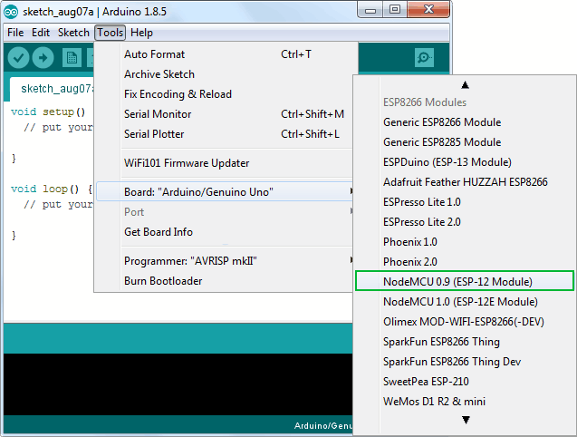 Рисунок 9 – Выбор отладочного модуля NodeMCU в Arduino IDE
Теперь подключите ESP8266 NodeMCU к компьютеру через USB-кабель micro-B. Как только плата будет подключена, ей должен быть назначен уникальный COM-порт. На компьютерах с Windows это будет что-то вроде COM#, а на компьютерах Mac/Linux он будет в виде /dev/tty.usbserial-XXXXXX. Выберите этот последовательный порт в меню Инструменты → Порт. Также выберите скорость загрузки: 115200
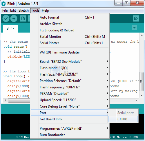 Рисунок 10 – Выбор COM порта в Arduino IDE
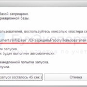
Предупреждение
Уделите больше внимания выбору платы, выбору COM порта и скорости загрузки. В случае некорректных настроек при загрузке новых скетчей вы можете получить ошибку espcomm_upload_mem.
После выполнения всех настроек попробуйте пример скетча, приведенного ниже.
После загрузки кода светодиод начнет мигать. Возможно, чтобы ваш ESP8266 начал работать со скетчем, вам придется нажать кнопку RST.
 Рисунок 11 – Рабта тестового скетча Blink на ESP8266 NodeMCU
Настройка облачной части для работы с устройством
Оставим на какое-то время наше устройство и создадим его двойник в облаке. С недавних пор двойник устройства можно создать прямо на портале Azure, воспользовавшись новыми возможностями. В группе настроек IoT-хаба под названием Explorers необходимо выбрать IoT Devices и нажать .
Для подключения устройства к IoT-хабу нам необходимо сгенерировать SAS (shared access signature). Для генерации SAS используется ключ двойника устройства, который можно получить с помощью вспомогательной утилиты (Device Explorer, iothub-explorer, IoT Extension for Azure CLI 2.0). Но проще всего получить ключ все там же, на портале Azure, зайдя в IoT Hub → IoT Devices.
IoT Explorer
SAS можно сгенерировать на устройстве, а можно с помощью своего онлайн-сервиса. В принципе, SDK может сгенерировать SAS автоматически (достаточно в коде указать ключ двойника устройства).
Создание токена с помощью сервиса
Способ, при котором SAS-токен генерируется веб-сервисом на ограниченное время, чуть более безопасен. Хотя существует и определенный нюанс. Если отправлять сервису только имя устройства, то злоумышленник может перебором имен получить токен какого-то другого устройства. Поэтому, чтобы немного обезопасить процесс, предлагаю такое решение: сохраним на устройстве хеш Azure-ключа двойника устройства. И в коде сервиса перед генерацией SAS проверим, совпадает ли хеш с хешем ключа устройства. Таким образом, получить SAS можно будет, только зная имя устройства и хеш его ключа.
Первый способ, при котором SAS генерируется на устройстве, более простой и удобный, но чуть менее безопасный, так как, получив доступ к устройству, злоумышленник сможет добыть ключ и генерировать SAS устройства самостоятельно. Во втором случае взломщик сможет получать только SAS токены, время жизни которых ограничено.
Выходит, что оба способа по большому счету неидеальны, если у хакера есть доступ к устройству. Даже защита соединения с помощью VPN здесь не поможет. В таком случае канал передачи будет защищен, но тот, кому попадет в руки устройство, сможет получить и доступ к каналу. К сожалению, на устройствах NodeMCU, Arduino и подобных нет возможности хранить ключи/пароли в каком-либо безопасном хранилище.
node.sleep()
Put NodeMCU in light sleep mode to reduce current consumption.
- NodeMCU can not enter light sleep mode if wifi is suspended.
- All active timers will be suspended and then resumed when NodeMCU wakes from sleep.
Attention
This is disabled by default. Modify in to enable it.
Parameters
- 1-12, pin to attach wake interrupt to. Note that pin 0(GPIO 16) does not support interrupts.
-
type of interrupt that you would like to wake on. (Optional, Default: )
- valid interrupt modes:
- Rising edge
- Falling edge
- Both edges
- Low level
- High level
- valid interrupt modes:
- Callback to execute when WiFi wakes from suspension. (Optional)
-
preserve current WiFi mode through node sleep. (Optional, Default: true)
- If true, Station and StationAP modes will automatically reconnect to previously configured Access Point when NodeMCU resumes.
- If false, discard WiFi mode and leave NodeMCU in . WiFi mode will be restored to original mode on restart.
Прошивки для esp8266 NodeMcu
В основу платформы загружена стандартная прошивка Node MCU, в которую встроен интерпретатор языка Lua. При помощи Lua-команд можно выполнять следующие действия:
- Подключение к Wi-Fi точке доступа;
- Работа в роли Wi-Fi точки доступа;
- Переход в режим глубокого сна для уменьшения потребления энергии;
- Включение или выключения светодиода на выходе GPIO16;
- Выполнение различные операции с файлами во флэш-памяти;
- Поиск открытой Wi-Fi сети, подключение к ней;
- Вывод MAC адреса;
- Управление пользовательскими таймерами.
Для программирования NodeMCU можно использовать Arduino IDE или комплекс средств разработки SDK – ESPlorer. Этот комплекс обладает рядом отличий:
- Он может работать на множестве различных платформ;
- Обладает поддержкой нескольких открытых файлов;
- Позволяет подсвечивать код языка Lua;
- Возможность умной отправки файлов;
- Возможность поддержки нескольких видов прошивки одновременно.
Для обеспечения корректной и стабильной работы нужно обновить прошивку до последней версии. Существует несколько способов обновления – облачный сервис, Docker Image и компилирование в Linux. Каждый из этих способов обладает своими плюсами и минусами. Наиболее простым и понятным является первый способ.
Сбор прошивки в облачном сервисе
После начала сборки придет письмо на почту, сигнализирующее о начале запуска процесса. Через некоторое время придет и второе письмо – будет предложено выбрать версию float (дробные числа) или integer (целые числа).
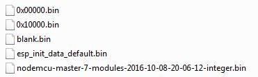
После перехода по полученной ссылке нужно будет скачать файл bin и поместить его в Resources – Binaries. Там будет расположен файл nodemcu_integer_0.9.5_20150318.bin, который нужно удалить. В итоге содержимое папки будет выглядеть следующим образом.
Обновление прошивки Node Mcu
Для правильной и стабильной работы платы требуется перезаписать esp_init_data_default.bin. Скачать его можно на официальном сайте. Нужный файл нужно поместить снова в систему для прошивки NodeMCU Flasher по пути Resources – Binaries, предварительно удалив из него старый файл.
Затем можно подключать NodeMCU и приступить к обновлению. Для начала нужно поменять настройки – в NodeMCU Flasher во вкладке Config нужно выбрать файл собранной прошивки вместо INTERNAL://NODEMCU.
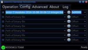
Остальное оставить без изменений, перейти на Operations и нажать Flash. Как только окончится прошивка, нужно снова перейти на Config и в первой строке указать путь esp_init_data_default.bin. Также дополнительно указывается адрес, куда нужно переместить этот файл. Для модуля NodeMCU следует выбрать адрес 0x3FC000. После этого нужно снова вернуться на Operations и нажать Flash.
После этого нужно переформатировать всю файловую систему млаты. Для этого нужно запустить ESPlorer, обязательно поставить скорость обмена 115200 и перезагрузить NodeMCU. После всех вышеописанных действий будет новая версия прошивки. Отладочная плата полностью перепрошита и готова к работе.
Step 7: GPIO
Analog-to-Digital Converter (ADC)
The Esp32 integrates 12-bit ADCs and supports measurements on 18 channels (analog-enabled pins). The ULP-coprocessor in the ESP32 is also designed to measure voltages while operating in sleep mode, which allows for low power consumption. The CPU can be awakened by a threshold setting and / or through other triggers.
Digital-to-Analog Converter (DAC)
Two 8-bit DAC channels can be used to convert two digital signals to two analog voltage outputs. These dual DACs support the power supply as an input voltage reference and can drive other circuits. Dual channels support independent conversions.
Connect to MQTT broker
-- init mqtt client with keepalive timer 120sec
m = mqtt.Client("clientid", 120, "user", "password")

-- setup Last Will and Testament (optional)
-- Broker will publish a message with qos = 0, retain = 0, data = "offline"
-- to topic "/lwt" if client doesn't send keepalive packet
m:lwt("/lwt", "offline", , )

m:on("connect", function(con) print("connected") end)
m:on("offline", function(con) print("offline") end)

-- on publish message receive event
m:on("message", function(conn, topic, data)
  print(topic .. ":")
  if data ~= nil then
    print(data)
  end
end)

-- m:connect(host, port, secure, auto_reconnect, function(client) end)
-- for secure: m:connect("192.168.11.118", 1880, 1, 0)
-- for auto-reconnect: m:connect("192.168.11.118", 1880, 0, 1)
m:connect("192.168.11.118", 1880, , , function(conn) print("connected") end)

-- subscribe to topic with qos = 0
m:subscribe("/topic", , function(conn) print("subscribe success") end)
-- or subscribe multiple topics (topic/0, qos = 0; topic/1, qos = 1; topic2, qos = 2)
-- m:subscribe({["topic/0"]=0,["topic/1"]=1,topic2=2}, function(conn) print("subscribe success") end)
-- publish a message with data = hello, QoS = 0, retain = 0
m:publish("/topic", "hello", , , function(conn) print("sent") end)

m:close();  -- if auto-reconnect == 1, it will disable auto-reconnect and then disconnect from host.
-- you can call m:connect again
Introduction: ESP32: Internal Details and Pinout
By Fernando KoyanagiVisit my Site!Follow
More by the author:
About: Do you like technology? Follow my channel on Youtube and my Blog. In them I put videos every week of microcontrollers, arduinos, networks, among other subjects.
More About Fernando Koyanagi »
In this article, we will talk about the internal details and the pinning of ESP32. I will show you how to correctly identify the pins by looking at the datasheet, how to identify which of the pins work as an OUTPUT / INPUT, how to have an overview about the sensors and peripherals that the ESP32 offers us, in addition to the boot. Therefore, I believe that, with the video below, I will be able to answer several questions that I have received in messages and comments about the ESP32 references, among other information.