Проектирование печатной платы в easyeda
Содержание:
Why are there different models for the same device?
Because each family of devices (resistors, diodes, bjts, jfets, MOSFETs etc.) is described by one or more sets of equations, each family has one or more models available for it.
One reason there are different models available for devices in the same family is because manufacturers give device models away for free. Therefore they do not want to spend any more time on developing device models than they need to. Basically, the more complex a model is, the more time the manufacturer has to spend on making measurements in order to derive the model parameters. Therefore if one manufacturer feels that a device can be adequately described by a simple model then they will use that rather than a more accurate but more complex and so more expensive one that may be available from a different manufacturer.
Another reason there may be differences between models of the same device is that there may be slight differences in the semiconductor fabrication processes of different manufacturers.In the same way ththeyat there may be more than one .model available for a device. there may be different .subckt defined models available.
There may be differences between .subckt models because there are implementation differences in the device models and/or the physical devices from different manufacturers. For example there are slight differences in internal timings and even a subtle difference in the internal circuitry of the oscillator section of the UC384x family of SMPS controllers between the various different manufacturers.
Sometimes, there are differences in the models just to get around the copyright protection. Some differences are to optimise the model for a particular simulator and some differences are simply down to the preferences of the model writer.
All document
| DocType | Shortcut | Function |
|---|---|---|
| All | Space | Rotate selected objects |
| All | Right-Click | Keep right-click to pan canvas; Open offset dialog when select one object |
| All | Left | Scroll Or Move selected left |
| All | Right | Scroll or Move selected right |
| All | Up | Scroll or Move selected up |
| All | Down | Scroll or Move selected down |
| All | TAB | Change object’s attributes when placing; Open offset dialog when select a object |
| All | Esc | Cancel current drawing |
| All | Home | setting new canvas origin |
| All | Delete | Delete Selected |
| All | F1 | Open tutorials |
| All | F11 | Full screen at browser |
| All | A | Zoom In |
| All | Z | Zoom Out |
| All | D | Drag |
| All | K | Fit Window |
| All | R | Rotate selected objects |
| All | X | Flip Horizontal(doesn’t support footprint) |
| All | Y | Flip Vertical(doesn’t support footprint) |
| All | ALT+F5 | Full screen at browser |
| All | CTRL+X | Cut |
| All | CTRL+C | Copy |
| All | CTRL+V | Paste |
| All | CTRL+A | Select All |
| All | CTRL+Z | Undo |
| All | CTRL+Y | Redo |
| All | CTRL+S | Save |
| All | CTRL+F | Find Component |
| All | CTRL+D | Design Manager |
| All | CTRL+Home | Open canvas origin setting dialog |
| All | SHIFT+1 | Cycle forward to next open tabbed document |
| All | SHIFT+2 | Cycle backward to next open tabbed document |
| All | SHIFT+X | Cross Probe |
| All | SHIFT+F | Search Library |
| All | SHIFT+Drag | Cursor snap to part’s origin |
| All | SHIFT+ALT+H | Align horizontal centers |
| All | SHIFT+ALT+E | Align verticas centers |
| All | CRTL+SHIFT+L | Align left |
| All | CRTL+SHIFT+R | Align right |
| All | CRTL+SHIFT+O | Align top |
| All | CRTL+SHIFT+B | Align bottom |
| All | CRTL+SHIFT+G | Align grid |
| All | CRTL+SHIFT+H | Distribute Horizontally |
| All | CRTL+SHIFT+E | Distribute Vertically |
| All | CTRL+SHIFT+F | Find similar objects |
Behavioural models
Using Behavioural Voltage and Current Sources and expressions it is possible to create what are called behavioural models of components. These are models that behave like a device but which have little or none of the actual underlying realistic circuit defined and are mostly — or perhaps completely — described by explicitly defined expressions (equations). The models for most devices internally comprising more than one active component, i.e. ICs, are largely behavioural. This is a way of hiding the detailed information about the manufacturer’s process technology that low level spice modelling reveals.
The use of expressions and behavioural sources in EasyEDA is explained later in the book.
Check the DRC Error
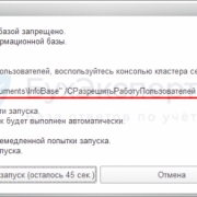
Via “Design Manager — DRC Error“ or “Top Menu — Design — Check DRC“, click the refresh icon to run the DRC. If your PCB is a big file, and have the copper area that will take some times to check the DRC, please wait a while.
After checking, you can view all the error at the “DRC Error”, click the error the related objects will be highlighted.
DRC error type
Clearance: Object to Object. If two different net objects too close, and the distance less than the Design Rule clearance, it will show the Clrearance error.
Track Length: The track Length of the all same net tracks must less than Design Rule track Length.
Track Width: The track width must must large than Design Rule track width.
-
Via Diameter: The via diameter must large than Design Rule diameter.
-
Via Drill Diameter: The via drill diameter must large than Design Rule drill diameter.
Note:
- When you convert a schematic to PCB, the real time DRC is enable. But in the old PCB, the real time DRC is disable. you can enable it in the image as above.
- Design rule checking can only help you find some obvious errors.
- The color of the DRC error can be set in the layer manager.
The Navigation panel is very important for EasyEDA: The part that you can find all your projects, files, parts and footprints.
Project
Here, You can find all of your projects that are private or shared with the public, or fork from someone else’s. These options have a content menu when you drop down to Projects and right click an item, you will get a tree menu like :
EELib
EElib means EasyEDA Libraries, It provides lots of components completed with simulation models, many of which have been developed for EasyEDA to make your simulation experience easier.
Design Manager
Design Manager, you can check each component and net easily, and it will provide DRC(Design rule check) to help your design better.
Library
Contains schematic symbols and PCB footprints for many available components and projects and your own libs and modules will show up here.
-
LCSCIf you want to buy components to finish your PCBA, you should try the LCSC module, LCSC.com and EasyEDA are the same company.EasyEDA partners with China’s largest electronic components online store by customers and ordering quantity launch https://lcsc.com.LCSC means Love Components? Save Cost! We suggest to our users to use LCSC parts to design. Why?
- Small Quantity & Global Shipping.
- More Than 25,000 Kinds of Components.
- All components are genuine.
- It is easy to order co after design.
- You can save 40% cost at least.
- You can use our components’ symbols and footprint directly in EasyEDA editor.
-
JLCPCBJLCPCB.com, LCSC.com and EasyEDA are the same company group. https://jlcpcb.comMore than 200,000 customers worldwide trust JLC, 8000 + online orders per day,JLCPCB (Shenzhen JIALICHUANG Electronic Technology Development Co.,Ltd.), is the largest PCB prototype enterprise in China and a high-tech manufacturer specializing in quick PCB prototype and small-batch production.Affordable, series quality boards fully manufactured in China. Fully e-tested. Transparent pricing.
Gerber View
Before sending Gerber to the factory, please use gerber viewer to check the Gerber carefully.
local gerber viewer you can use such as: Gerbv, FlatCAM, CAM350, ViewMate, GerberLogix etc.
Gerber viewer recommend Gerbv:
- Project page:http://gerbv.geda-project.org/
- Download: https://sourceforge.net/projects/gerbv/files/
How to use Gerbv:
1.Download Gerber zip file, and download Gerbv, unzip Gerber file and run the Gerbv;
2.Click the button at the Gerbv dialog bottom-left corner, open the gerber folder, select all the gerber files, and open.
3.And then zoom, measure, check every layer, check drill holes and location. etc.
FlatCAM is a nice tool too: http://flatcam.org/
FlatCAM lets you take your designs to a CNC router. You can open Gerber, Excellon or G-code, edit it or create from scatch, and output G-Code. Isolation routing is one of many tasks that FlatCAM is perfect for. It’s is open source, written in Python and runs smoothly on most platforms.
Free Online Gerber Viewer:
Recommend:jlcpcb.comtracespace.io/viewgerber.ucamco.com
Cloud Auto Router
For some simple or prototype PCBs, you may want to use the auto router function to save time. Layout is a time costly and dull job. EasyEDA spends lots of time to provide such a feature and it is loved by our users.Before using the auto router, you need to set the board outline for the PCB.
Auto router is not good enough! Suggest routing manually! You can use “RoundTrack(Walk Arroud)” option to route tracks, via right-hand panel — Routing Conflict.
Steps:
1 Click the the auto router button from the Top Menu”Top Menu> Route > Auto Router”
2 Config the auto router
After you click that button, you will get a config dialog like in the image below.
In the config dialog, you can set some rules to make the auto router result professional. These rule must equalize or more than DRC setting.
General Options
- Unit: The unit follows PCB canvas unit.
- Track width: The auto-route track width.
- Clearance: The clearance of the objects.
- Via Diameter/Via Drill Diameter: The via placing by auto-router.
- Realtime Display: when you select it , the real time routing status will show on.
-
Router Server:
- Cloud: Using EasyEDA online server.
- Local: Using the local auto router server, when you click the Auto Router icon, the editor will check the local router server available or not automatically. How to use please see as below.
- Router Layers: If you want to route inner layer, you have to enable the inner layer first.
- Special Nets: For the power supply track, you may want it to be bigger, so you can add some special rules.
- Skip Nets: If you like to keep the a net with no route, you can skip it. For example, if you want to use copper area to connect net, you can skip the net. If you want to reserve the routed track, you need to select the .
3 Run it
After click the “Run” button , The real time check box will let you see how it is going, but it will make the process a little bit slow.
Waiting for a few minutes, after adding bottom and top copper area, you will get a finished PCB board.
When finish, will pop up a window.
The connection means the track connect times.
Notice:
The parameter can’t less than DRC rule, otherwise will report error.
Создание нового проекта в EasyEDA
Проект в EasyEDA — это совокупность схем и данных о разметке вашей платы. Так что если вы планируете даже просто нарисовать схему, то вы должны создать новый проект и уже в нем создать новую схему. Это может показаться лишним действием, однако приучит вас к порядку раскладывать все по папочкам. У вас же не лежат все документы на рабочем столе без папок? Или все таки да 🙂
Новый проект можно создать «с нуля» или склонировать у кого-то уже существующий (как это сделать будет показано ниже). Также кто-то может предоставить вам доступ к своему проекту для совместной работы.
Создание вашего первого проекта в EasyEDA
Создание нового проекта в EasyEDA
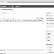
Далее вам предлагается ввести название проекта и указать: будет ли ваш проект публичным (проект будет доступе в поиске и кто угодно сможет его склонировать себе в редактор и производить над копией любые действия), либо ваш проект будет приватным и посторонние не получат к нему доступа до тех пор, пока вы этого не захотите. Публичность/приватность проекта можно менять в последующем неограниченное количество раз.
Задайте подробное описание вашего проекта в поле Description.
Выберите тип вашего проекта: приватный или публичный
.model statements
In the spice netlist of a circuit, the user can see the models listed in .model statements. When a schematic is saved, these .model statements are pulled in to the netlist by EasyEDA recognising the symbols and their associated device names given in the schematic. Each model may either be pulled in from a library or — for devices that are not in the EasyEDA libraries — by downloading a model from a manufacturer’s website and then manually pasting it directly into the schematic (the process of doing this will be described later).
Ngspice model types
To help identify model types and in particular if they are for N or P type devices, the following table of model types may be helpful.
| Code | Model Type |
|---|---|
| R | Semiconductor resistor model |
| C | Semiconductor capacitor model |
| L | Inductor model |
| SW | Voltage controlled switch |
| CSW | Current controlled switch |
| URC | Uniform distributed RC model |
| LTRA | Lossy transmission line model |
| D | Diode model |
| NPN | NPN BJT model |
| PNP | PNP BJT model |
| NJF | N-channel JFET model |
| PJF | P-channel JFET model |
| NMOS | N-channel MOSFET model |
| PMOS | P-channel MOSFET model |
| NMF | N-channel MESFET model |
| PMF | P-channel MESFET model |
Although it is beyond the scope of this document to go into detail there are some other points about models that are worth mentioning.
- Models for the basic resistors, capacitors and inductors used in a schematic are usually not shown in the netlist;
- Some device models have a full list of parameters, some may only have a partially completed list. Missing parameters in models are simply replaced by default values.
- Different simulators support different sets of models so in some cases the simulator may warn the user that some parameters are unrecognised and so are ignored. This often has little effect on the simulation results but if the user is particularly concerned about their effects then the only options are to find a model which only uses parameters recognised by ngspice or change to using a simulator (such as LTspice) that supports all the relevant parameters.
Multi-part Components
The number of pins on some components can be quite large. That’s why it’s easier to divide such a component into several parts or functional blocks.
As a simple example, there are six gates in the 74HC04 Hex Inverter component. To avoid clutter in the schematic, GND and VCC pins of such components are usually served by a separate part of the component. This is really convenient as it doesn’t interfere the working process with logical parts. The NetLabel names of VCC and GND Pin are usually hidden.
When placing the 74HC04 on a schematic, it will look like the screenshot below.
Note: The component Prefix will be in form of: U?.1, U?.2 etc.
How to create multi-part(subpart) please refer Create Symbol
Generate Fabrication File Gerber
When you finish your PCB, you can output the Fabrication Files(gerber file) via: File > Generate PCB Fabrication File(Gerber) , or Fabrication > PCB Fabrication File(Gerber).
After clicking, will open the Gerber generate dialog:
You can calculate the price for the PCB order, click SAVE to CART will go to JLCPCB and add your PCB in the cart.
Gerber file name
The generated Gerber file is a compressed zip file. After decompression, you can see the following files:
- Gerber_BoardOutline.GKO:PCB Border file. The PCB board factory cuts the shape of the board according to this document. The groove drawn by the EasyEDA, the solid region(Type: NPTH) is reflected in the border file after the Gerber is generated.
- Gerber_TopLayer.GTL:Top side copper layer.
- Gerber_BottomLayer.GBL:Bottom side copper layer.
- Gerber_Inner1.G1,Gerber_Inner2.G1… :Inner copper layer.
- Gerber_TopSilkLayer.GTO:Top silkscreen.
- Gerber_BottomSilkLayer.GBO:Bottom silkscreen.
- Gerber_TopSolderMaskLayer.GTS:Top solder mask. The default board is covered with green oil, and the elements drawn on this layer correspond to the top layer’s area will not be covered with oil.
- Gerber_BottomSolderMaskLayer.GBS:Bottom solder mask. The default board is covered with green oil, and the elements drawn on this layer correspond to the bottom layer’s area will not be covered with oil.
- Gerber_Drill_PTH.DRL:Plated drill through hole layer. This document shows the location of the hole where the inner wall needs to be metallized.
- Gerber_Drill_NPTH.DRL:Non-Plated drill through hole layer. This document shows the location of the hole where the inner wall don’t need to be metallized.
- Gerber_TopPasteMaskLayer.GTP:Top Paste Mask, for the stencil.
- Gerber_BottomPasteMaskLayer.GBP:Bottom Paste Mask, for the stencil.
- ReadOnly.TopAssembly:Top Assembly, read only, doesn’t affect the PCB manufacture.
- ReadOnly.BottomAssembly:Bottom Assembly, read only, doesn’t affect the PCB manufacture.
- ReadOnly.Mechanical:Record the information on the mechanical layer in the PCB design, and only use it for information recording. By default, the shape of the layer is not manufactured at the time of production. Some board manufacturers use the mechanical layer to make the frame when using Altium file to production. When using Gerber file, it is only used for text identification in JLCPCB. For example: process parameters; V cut path etc. In EasyEDA, this layer does not affect the shape of the border of the board.
Notice:
- Before ordering the PCB, please check the gerber at the Gerber view as below.
- The Gerber files are generated by browser, please use the browser inner downloader to download!
Library
EasyEDA provide a lot of libraries, you can find them at “Left-hand Panel — Library”, hotkey “SHIFT+F”, at here you can search library from LCSC, system, user contributed etc.
Type
- Symbol: Schematic symbols
- Spice Symbol: Symbols for spice simlation
- Footprint: PCB footprints, PCB pattern.
- SCH Modules: Schematic modules, a part of the circuit design. It can not assign the PCB module, doesn’t like the schematic Symbol can assign the footprint . when it be placed on the schematic, it will be separated.
- PCB Modules: As like as Schematic modules.
- 3D Model: It is bind with footprint via “3D Model Manager”.
Classes
- Work Space: It include your personal parts and your teams’ parts.
- LCSC: EasyEDA online part store LCSC.com parts(Officail Parts). It will add new libraries everyday
- LCSC Assembled: JLCPCB Assembled parts. All JLCPCB assembly parts will contain a SMT icon, that means this part can be JLCPCB assemble.
- System: EasyEDA system parts, it comes from open source libraries, such as Kicad libraries, company public libraries, user contributions.
- Follow: If you follow a user at EasyEDA(You can follow a user at him/her user page), you can view and use his/her libraries.
- User Contributed: When you searching a part, maybe you can find it at this class. At EasyEDA, all libraries are public. the detail you can refer at: Contribute
We add an “JLCPCB Assembled” Components option of the Parts, It’s easy to choose which component can be assembled by JLCPCB. Yes, JLCPCB will provide the assembly service. the more information please refer at: How to order a SMT order
Search Engine — EasyEDA
Simply type your part number or symbol’s name to Search. before searching, you must choose the “Type” first.
and then click the “Table of contents” to open the categories list to choose your components.
From there you can scroll up and down to browse parts from each category.
If you know the component’s nameSuppose you want to find the MAX232 (which converts signals from an RS-232 serial port to signals suitable for use in TTL compatible digital logic circuits). Simply type Max232 into the Search box and press Enter:
- If you don’t know the component’s nameFor example, you want to find a resistor which value is 1kohm, footprint is 0603, at Libraries you can follow below steps:
- 1.Choose the library type
- 2.Typing the keyword such as
- 3.Click the search button
- 4.Select the class you which is wanted of the result
- 5.If you don’t need the search you need to remove all the search keywords
Search Engine — LCSC Electronics
When you want to find some parts by clearly parameter, you should try “Search Engine — LCSC Electronics”, it all most same as LCSC.com.
When you find out part, and you can place into the schematic:
Notice:
The subpart can not be preview at Preview dialog window, if you find out this, you need to change to “Search Engine — EasyEDA” to place this part.
Max and Min mode
If you want to place without close the “Library” dialog, you can change dialog mode to Min mode, just click the Min button at the top-right corner.
Operations
When you hover the mouse over the picture of the Schematic symbol or PCB footprint, you will find a toolbar with “Edit”, “Place”, “More” buttons.
Place:
For parts you use infrequently, you don’t need to Favorite them; just Place it into your canvas directly. Or you can double click the library to place.
Note:
-
EasyEDA supports multi-documents so please make sure that you are placing the part into the right (active) document. The active document is the one with the highlighted tab.
-
You can’t place a Schematic symbol into a PCB file, or a PCB Footprint into a schematic.
-
EasyEDA will try the best to make sure the library is correct, but it still has incorrect parts, if you find any incorrect parts please let us known. suggested order a sample first before ordering a big order.
Edit:
If you want to create your own version of a symbol or footprint then you can open an existing part from the library to use as a template, edit it and then save it to your local Work Space library in Library of the Navigation Panel.
More:
We can’t promise that every component in the library is free of errors so please check all symbols and footprints carefully before you commit to a PCB order.
If you do find a mistake in a component, please use the , so that we can fix it.
Components with sub parts (multi-device footprints).
When you find a component with sub-parts, you can’t Place or Edit it, but you can Favorite and Clone it as your own part, which you can then edit.
Right-Click
When you right-click the part list, you can edit its tags, add favorite etc.
Preview Image
Every library when you click, you can check its preview image, such as symbol, footprint, production picture. Click the the image you can open it quickly.
Layout Single Layer PCB
The PCB copper layers of EasyEDA are double, EasyEDA doesn’t support layout a signle layer directly. if you want to layout a single layer PCB(such as only layout on the bottom layer),
There are two methods:
Method 1:
- Route the track and copper on the bottom layer, and without placing via.
- If you are using the footprints which have the multi-layer pads, that will appear on the top and bottom layer, then you need to change all multi-layer pads “Plated” as “No”.
- Generate the Gerber, decompress the Gerber zip file, delete the layers which you don’t need(such as Gerber_TopLayer.GTL, Gerber_TopSilkLayer.GTO, Gerber_TopSolderMaskLayer.GTS, Gerber_TopPasteMaskLayer.GTP).
- And re-compress the Gerber to a zip file, and order it.
Method 2:
- Design your PCB at one side, if other side has pads etc, you don’t need to deal with them.
- Generate the Gerber.
- Add the comment for mention that you need to order the signle layer PCB when order the PCB.